

Why Is Your LVDS to TTL Signal Conversion Board Not Outputting a Stable Signal
2026-11-12
When a display system starts showing flickering images, random color shifts, or intermittent blank screens, the fault often traces back to signal instability at the interface stage. A LVDS to TTL Signal Conversion Board sits between the low-voltage differential signaling source and the TTL-driven panel, and any weakness in that link quickly shows up on screen. At SKY-TDM, engineers routinely diagnose these faults across industrial monitors, medical displays, and embedded terminals, and the causes tend to fall into a small set of repeatable categories.
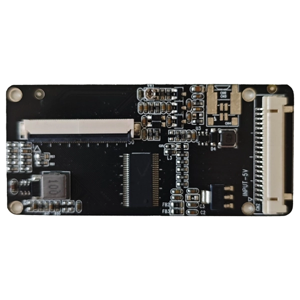
Common Causes of Unstable Output
| Cause Category | Typical Symptom | Root Issue |
|---|---|---|
| Power supply noise | Flicker, horizontal bands | Ripple on VCC exceeding board tolerance |
| Impedance mismatch | Ghosting, weak contrast | Trace routing or cable impedance off 100 Ω |
| Clock and data skew | Color errors, shifted image | Pair length mismatch or poor twisting |
| Grounding problems | Random dropouts | Ground loop or insufficient return path |
| Connector and cable faults | Intermittent signal loss | Loose FPC, bent pins, worn contacts |
| Configuration mismatch | No image or wrong resolution | Incorrect jumper or firmware mapping |
Diagnostic Checklist
-
Measure the input supply with an oscilloscope; ripple should stay well within the LVDS to TTL Signal Conversion Board specification.
-
Verify that differential pairs maintain consistent 100 Ω impedance from source to board.
-
Confirm pair-to-pair length matching to keep skew within the receiver's sampling window.
-
Inspect grounding: a single low-impedance return path prevents circulating currents.
-
Reseat and test every connector, then swap cables to isolate mechanical faults.
-
Check jumper and firmware settings against the panel datasheet.
Design Practices That Improve Stability
-
Keep differential traces short and symmetric, with matched via counts.
-
Place decoupling capacitors close to the conversion IC power pins.
-
Use shielded twisted-pair cables and terminate unused pairs properly.
-
Separate switching power components from sensitive analog and clock routing.
-
Validate thermal performance, since drifting temperature can shift timing margins.
SKY-TDM builds LVDS to TTL Signal Conversion Boards with controlled-impedance layouts, wide input tolerance, and reinforced connector retention, which reduces the marginal failures that appear in field deployments.
FAQ
Q: Why does my LVDS to TTL Signal Conversion Board output flicker only at high resolution?
A: Higher resolutions raise pixel clock frequency and compress the timing budget, so marginal impedance, skew, or power ripple that passes at low resolution becomes visible. Check trace matching, cable quality, and supply decoupling first.
Q: Can a faulty cable cause an LVDS to TTL Signal Conversion Board to lose signal intermittently?
A: Yes. Worn contacts, bent pins, and broken shields interrupt differential pairs, producing dropouts that mimic board failure. Swap the cable and reseat connectors before replacing the board.
Q: How do I confirm whether the problem is the LVDS to TTL Signal Conversion Board or the display panel?
A: Feed a known-good signal into the board and measure its TTL outputs with an oscilloscope or logic analyzer. Stable outputs point to the panel; unstable outputs confirm a board-side issue.
Q: Does power supply quality affect LVDS to TTL Signal Conversion Board stability?
A: Excess ripple and voltage sag disturb the internal receiver thresholds, causing jitter and banding. Use a clean regulated supply and add local decoupling near the board input.
For technical support, sample requests, or integration guidance on LVDS to TTL Signal Conversion Boards, contact us at SKY-TDM today and let our engineering team help you lock in a stable signal path.