

Why Is My Digital Ultrasonic Generator Not Delivering Rated Power Under Load Conditions
2026-08-11
When an industrial ultrasonic cleaning system underperforms, the culprit is often the Digital Ultrasonic Generator failing to output its specified wattage under real-world load. At Clangsonic Ultrasonic, we have diagnosed thousands of such cases, and the root cause is rarely a single component—it is almost always an interaction between the generator, the transducer, and the cleaning solution. This guide walks through the seven most common failure modes, their diagnostic signs, and proven corrective actions.
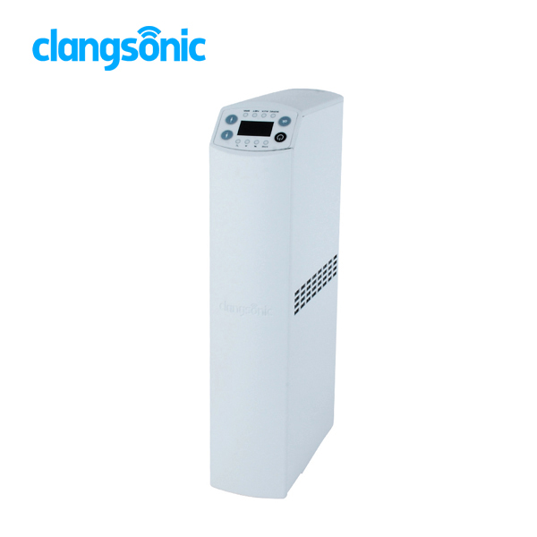
The Load–Power Paradox
A Digital Ultrasonic Generator is rated at a certain power (e.g., 1000W) under ideal lab conditions—stable temperature, pure water, and a perfectly tuned transducer. In production, the load changes constantly: tank liquid level fluctuates, parts baskets absorb energy, and transducers age. The generator must continuously adjust its output via closed-loop impedance control. If that loop breaks, power drops.
7 Diagnostic Checkpoints (Quick Reference)
| Checkpoint | What to Measure | Acceptable Range |
|---|---|---|
| 1. Input Mains Voltage | AC at generator terminal | Rated voltage ±10% |
| 2. Transducer Capacitance | With LCR meter at 1kHz | Within ±15% of factory spec |
| 3. Cable Resistance | Loop resistance (out + return) | < 0.5 Ω per metre |
| 4. Liquid Temperature | Thermocouple in tank | 50–70°C (stable) |
| 5. Sweep Bandwidth | Generator display or oscilloscope | ±2% of centre frequency |
| 6. Reflected Power | Forward/reflected RF reading | Reflected < 10% of forward |
| 7. Cooling Airflow | Anemometer at intake vent | > 2 m/s |
Most Frequent Causes (Ranked by Probability)
| Rank | Cause | Typical Power Loss | Fix |
|---|---|---|---|
| 1 | Detuned transducer (capacitance drift) | 30–50% | Re-tune or replace transducer stack |
| 2 | High cable impedance (too long or thin) | 20–40% | Use shielded twisted pair, < 5 m length |
| 3 | Solution overheating (≥75°C) | 25–35% | Install cooling coil or reduce duty cycle |
| 4 | Faulty MOSFET/IGBT bank (partial short) | 40–60% | Replace power module with Clangsonic Ultrasonic certified kit |
| 5 | Incorrect sweep settings (too wide) | 15–25% | Set sweep to ±1.5% of resonant frequency |
| 6 | Water level too low (exposes transducers) | 10–20% | Maintain level ≥ 10 cm above tank bottom |
| 7 | Dirty heat sink (thermal throttling) | Gradual drop | Clean fins and reapply thermal paste |
The 5-Step Resolution Protocol
-
Isolate the load – Run the Digital Ultrasonic Generator in air (no liquid). If rated power returns, the issue is acoustic loading, not electronics.
-
Measure resonant frequency – Use an impedance analyser. A shift > 3% from factory setting means the transducer needs mechanical re-tightening or replacement.
-
Check the tracking loop – Enable auto-frequency tracking on the Clangsonic Ultrasonic interface. Observe if the generator locks within 2 seconds. If it hunts continuously, the feedback capacitor is degraded.
-
Examine the waveform – Connect a current probe. A non-sinusoidal or clipped waveform indicates magnetic saturation in the output transformer.
-
Thermal test – Run at 50% power for 10 minutes, then at 100%. If power drops only at high load, the cooling fan is undersized or obstructed.
When to Replace vs. Repair
| Condition | Recommended Action |
|---|---|
| Single transistor failed | Repair – replace matched pair |
| PCB burnt track or swollen electrolytic capacitors | Repair – if board is not carbonised |
| Transformer humming with visible heating | Replace – core loss is irreversible |
| Generator older than 5 years with frequent faults | Upgrade to Clangsonic Ultrasonic new-gen model with digital adaptive tuning |
Frequently Asked Questions
Q1: Can a partially clogged ultrasonic transducer cause the Digital Ultrasonic Generator to reduce output power even when the display shows 100%?
A: Yes – and this is the most deceptive scenario. The generator measures its electrical output (voltage × current), not the mechanical energy transferred into the liquid. A delaminated or cracked transducer element converts electrical energy into heat instead of ultrasound. The generator "thinks" it is delivering full power, but cavitation intensity drops by over 50%. The only reliable diagnostic is to compare input electrical power (from the mains) with output RF power. If the difference exceeds 15%, the transducer is the primary suspect. Replace the transducer stack and re-run the auto-calibration routine available on all Clangsonic Ultrasonic generators.
Q2: Why does my Digital Ultrasonic Generator deliver rated power for the first 5 minutes and then gradually drop to 60%?
A: This classic thermal drift pattern points to two overlapping causes. First, the output MOSFETs heat up, increasing their internal on-resistance (Rds(on)) – this reduces efficiency. Second, the transducer's resonant frequency shifts downward as the cleaning solution warms up (speed of sound changes). If the generator's frequency tracking algorithm is too slow (update rate < 100 Hz), it cannot compensate in real time. The solution is to enable predictive temperature compensation – a feature where the generator monitors a thermistor in the tank and pre-adjusts the frequency before the drift occurs. For older units without this, reduce the setpoint to 80% and run continuously; or upgrade to a Clangsonic Ultrasonic generator with adaptive feed‑forward control, which maintains ±2% power stability from cold start to thermal equilibrium.
Q3: Does the length of the coaxial cable between the Digital Ultrasonic Generator and the transducer affect rated power delivery under heavy load?
A: Absolutely – and this is frequently overlooked. Every metre of standard RG58 cable adds approximately 0.2 Ω of series resistance and 30 pF of parallel capacitance. At 40 kHz, a 10‑metre cable introduces a phase shift of nearly 18°, which misaligns the voltage and current waveforms. The generator's power calculation assumes a resistive load; with reactive cable impedance, the apparent power (VA) increases while true power (watts) decreases. For full rated power delivery, keep the cable length under 3 metres and use low‑loss RG213 or specialised ultrasonic cable with capacitance < 50 pF/m. If longer runs are unavoidable, recalibrate the generator's output impedance matching network – a standard service offered by Clangsonic Ultrasonic during installation. Also verify that the cable is not coiled, as coiling increases inductive reactance and further derates output.
Final Verification
After applying the fixes above, perform a loaded power test with a standardised workload (e.g., 10 aluminium foils in the tank). Measure cavitation erosion area after 60 seconds – a healthy Digital Ultrasonic Generator will produce uniform pitting across at least 90% of the foil surface. If pitting is localised or weak, return to Step 1 and re‑evaluate the transducer bonding adhesive – it is the silent failure point that no electrical test catches.
Need Professional Assistance?
Diagnosing power loss in a Digital Ultrasonic Generator requires both RF engineering knowledge and hands‑on transducer experience. Clangsonic Ultrasonic offers a complete diagnostic service including on‑site impedance analysis, thermal imaging of power stages, and firmware health checks. If your generator still underperforms after following this guide, contact our technical support team today with your model number and load conditions – we will send you a pre‑paid return label for a free bench test, or schedule a remote session to log your generator’s internal parameters in real time. Do not let lost power cost you production hours – reach out now for a same‑day consultation.