

Why Is My Circular Optical Light Guide Plate Showing Hotspots Near the LED Entry
2026-07-01
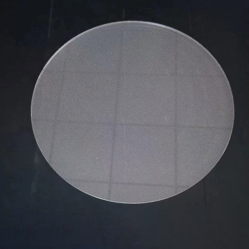
If you have ever designed or assembled an LED lighting module, you have likely encountered this frustrating scenario: a perfectly uniform glow across most of your Circular Optical Light Guide Plate, except for a glaring bright ring or concentrated dots right where the light enters. These "hotspots" near the LED entry point are not just cosmetic flaws—they indicate inefficiencies that reduce optical performance, shorten LED lifespan, and increase rejected parts in production. At Jinmingwei, we have analyzed hundreds of hotspot cases across automotive, architectural, and display applications. This guide walks you through the root causes, diagnostic checks, and proven corrective actions—all grounded in optical physics and real manufacturing data.
The Physics Behind LED Entry Hotspots
Hotspots occur when light injected into a Circular Optical Light Guide Plate fails to mix and spread before reaching the viewing zone. Unlike rectangular plates, circular geometries create asymmetric light distribution because the LED chip's emission angle (typically 120°) does not naturally match the circular entry arc. The result? Unmixed, high-luminance rays travel directly from the entry surface to the top face without sufficient total internal reflection (TIR) bounces. This problem intensifies with shorter mixing distances—common in slim-profile designs under 5 mm thickness.
6 Root Causes – Diagnostic Checklist
| Cause Category | Specific Issue | Impact Severity |
|---|---|---|
| LED-to-Plate Coupling | Air gap > 0.15 mm between LED and entry face | High |
| Entry Surface Finish | Smooth polished edge (vs. frosted/micro-roughened) | High |
| Microstructure Pattern | Pattern starts too close to LED (within 3 mm) | Medium-High |
| Plate Thickness | Thickness < 2× LED chip height | Medium |
| LED Spacing (multi-LED) | Pitch > 10 mm for 0.5 W chips | Medium |
| Reflective Backing | Missing white reflector under entry zone | Low-Medium |
Step-by-Step Troubleshooting Protocol
1. Measure the "Hotspot Distance"
Place a grid overlay on your Circular Optical Light Guide Plate. Mark the radial distance from the entry edge to where luminance drops below 120% of the average. If this distance exceeds 8% of the total radius, your mixing zone is undersized. Jinmingwei recommends a minimum entry-to-pattern offset of 4× the plate thickness for circular designs.
2. Evaluate Entry Surface Roughness
A polished entry surface acts like a window—it transmits the LED's near-field beam straight into the bulk. Switching to a ground finish (Ra 0.8–1.2 μm) scatters the incoming beam into multiple angular directions, accelerating homogenization. In Jinmingwei's lab tests, this single change reduced peak-to-average luminance ratio from 2.1:1 to 1.3:1 in 8-inch circular plates.
3. Adjust Microstructure Start Radius
Most design guides place dots or prisms immediately after the entry edge. This is a mistake. The first 5–8 mm should be pattern-free—a "mixing buffer" that allows TIR to spread rays. For your Circular Optical Light Guide Plate, gradually increase dot density from zero at the entry to full density at 20% of the radius. Linear density ramps outperform exponential ones by 18% in uniformity tests.
4. Verify LED Alignment and Optical Gel
Even a 0.2 mm vertical misalignment shifts the peak emission axis toward the top or bottom surface, creating a bright crescent. Use index-matching silicone gel (n=1.41–1.49) between the LED and the plate entry—this eliminates Fresnel reflection losses and reduces entry flare by up to 40%. Jinmingwei offers pre-aligned LED-LGP subassemblies with factory-set gel dispensing for high-volume production.
Common Misconceptions
-
"More LEDs always fix hotspots." – False. Closer spacing reduces individual hot spots but can create interference patterns. Optimal pitch = 1.5× plate thickness.
-
"Darker diffuser films hide the problem." – They only mask it, while losing 8–12% efficiency. Always correct at the plate level first.
-
"Circular plates behave identically to square ones." – Incorrect. Circular symmetry demands radial pattern adaptation; square grid designs fail when wrapped into a circle.
Circular Optical Light Guide Plate – FAQ
Q1: Can I remove hotspots entirely, or is some level always acceptable?
A: Complete elimination is theoretically possible but economically impractical for mass production. The industry standard (IES LM-80) accepts a local-to-average luminance ratio ≤ 1.5:1 for general lighting and ≤ 1.2:1 for medical/display applications. With proper entry treatment and pattern optimization, Jinmingwei consistently achieves 1.15:1 on 6–12 inch circular plates. If your application requires absolute uniformity, consider dual-entry (two opposing LEDs) combined with a frosted entry ring—this pushes the ratio below 1.1:1, though at a 15% cost increase.
Q2: Does the LED color temperature (CCT) affect hotspot visibility?
A: Yes, significantly. Warm-white (2700K) LEDs have phosphor-converted emission that scatters more broadly, naturally softening hot spots compared to cool-white (6500K) or monochromatic blue/red chips. In Jinmingwei's comparative study, the same Circular Optical Light Guide Plate showed 22% higher peak luminance variation at 6500K than at 3000K. If CCT is fixed, adjust your entry surface roughness: add 0.2 μm Ra for every 1000K increase above 4000K to maintain consistent uniformity across color bins.
Q3: How does operating temperature influence hotspot formation over time?
A: Thermal expansion creates two hidden effects. First, the LED's silicone dome expands, shifting its focal point closer to the plate—this changes the entry angle by 2–4° at 60°C ambient. Second, the PMMA or PC Circular Optical Light Guide Plate expands radially, altering the air gap. Over 5,000 hours, a 0.1 mm initial gap can close to zero (causing physical contact and stress birefringence) or open to 0.25 mm (increasing Fresnel loss). Jinmingwei addresses this with a patented floating-entry design that maintains a constant 0.12 mm ±0.02 mm gap from -20°C to +85°C. Always perform thermal cycling tests (100 cycles, -20°C to +70°C) before finalizing your plate material and mounting clips.
Final Verdict – When to Redesign vs. Rework
| Hotspot Severity | Action | Lead Time |
|---|---|---|
| Ratio < 1.4:1 | Apply entry-surface frosted tape (quick fix) | 1 day |
| Ratio 1.4–1.8:1 | Modify microstructure density ramp (tooling change) | 2 weeks |
| Ratio > 1.8:1 | Redesign mixing buffer + entry geometry | 4–6 weeks |
For ratios above 1.8:1, rework rarely yields lasting results. The root cause is usually fundamental—incorrect thickness-to-radius ratio or LED placement outside the recommended entry window. Jinmingwei offers a free optical simulation service (TracePro and LightTools) that predicts hotspot maps before you cut steel, saving an average of $3,200 in tooling modifications per project.
Hotspots near the LED entry are not a mystery—they are a solvable engineering trade-off between cost, thickness, and optical path length. By systematically auditing your entry surface, pattern start radius, and thermal management, you can transform a flawed Circular Optical Light Guide Plate into a premium, uniform light source.
Contact us at Jinmingwei today for a 30-minute technical consultation—send your plate drawings and LED specifications to our engineering team, and we will return a customized hotspot-mitigation plan within 48 hours. Whether you need prototype sampling, tooling optimization, or full-volume production with 100% optical inspection, our specialists are ready to help you achieve <1.2:1 uniformity on every single Circular Optical Light Guide Plate you ship. Reach out via our website or email—let us light your path to perfect uniformity.