

Why Does My LVDS to TTL Converter Board Show Timing Errors on High-Resolution Screens
2026-09-04
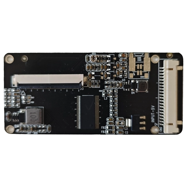
When integrating a legacy TTL-based display with a modern high-resolution panel, the LVDS to TTL Signal Conversion Board often becomes the critical link. However, engineers frequently encounter timing errors—manifested as flickering, horizontal tearing, or complete loss of sync—as resolution climbs beyond 720p. These errors are not random; they stem from fundamental mismatches in data rate, clock skew, and pixel clock stability. At SKY-TDM, we have analyzed hundreds of such failure cases and identified the root causes that every designer must understand.
1. The Pixel Clock Bottleneck
The most common culprit is the pixel clock (pCLK). A LVDS to TTL Signal Conversion Board typically operates within a specified pCLK range (e.g., 20–85 MHz). For a 1920x1080@60Hz display, the pixel clock exceeds 148 MHz. When the board’s internal PLL cannot lock to this frequency, timing parameters like Horizontal Front Porch and Vertical Sync Pulse drift outside the receiver’s tolerance.
| Resolution | Pixel Clock (MHz) | TTL Output Setup/Hold Margin | Error Probability |
|---|---|---|---|
| 800x600@60 | 40.0 | ±2.5 ns | Low |
| 1280x720@60 | 74.2 | ±1.8 ns | Medium |
| 1920x1080@60 | 148.5 | ±0.6 ns | High |
| 2560x1440@60 | 241.5 | Unstable | Critical |
As shown above, margin shrinks drastically. SKY-TDM recommends verifying the board’s maximum pCLK specification before selection—many low-cost converters omit this parameter entirely.
2. Skew Between Clock and Data Lines
TTL receivers sample data on the rising or falling edge of the clock. In high-resolution modes, the LVDS to TTL Signal Conversion Board must deserialize 4 or 7 LVDS lanes into parallel TTL data. If the board’s internal delay matching is poor, skew between the recovered clock and data can exceed 1 ns—enough to corrupt setup/hold times.
Common symptoms:
-
Vertical lines appear shifted every few rows.
-
Color channels (R/G/B) misalign at screen edges.
-
Errors intensify with temperature changes.
SKY-TDM uses automatic deskew circuits in its conversion boards, which dynamically adjust per-lane delays up to 2.5 ns, ensuring robust operation even at 1080p@60.
3. Inadequate Drive Strength and Termination
High-resolution TTL signals demand faster rise/fall times (< 2 ns). Many generic LVDS to TTL Signal Conversion Board designs use weak output drivers (e.g., 4 mA sink/source) with incorrect series termination. This causes ringing and reflections on the flat cable, which the display’s timing controller misinterprets as extra clock edges—directly producing timing errors.
Recommended countermeasures:
-
Use boards with programmable output drive (8–16 mA).
-
Add 22–33 Ω series resistors close to the TTL output pins.
-
Keep cable length under 30 cm for pCLK > 100 MHz.
4. Voltage-Level Mismatch
Modern high-res screens often run on 3.3 V TTL, while older panels use 5 V. A LVDS to TTL Signal Conversion Board that lacks proper level shifting may force the display’s input protection diodes into conduction, distorting the rising/falling edges asymmetrically. This distortion shifts the effective sampling point, creating intermittent timing errors that are heat-sensitive.
SKY-TDM boards feature dual-voltage I/O banks (1.8 V / 3.3 V / 5 V tolerant) with independent VREF pins, eliminating this variable from the timing budget.
5. Systematic Debugging Table
| Symptom | Likely Root Cause | SKY-TDM Solution |
|---|---|---|
| Tearing at top 20% of screen | Insufficient vertical back porch | Adjust front/back porch via internal registers |
| Random pixel shifting | Clock-data skew > 1.2 ns | Enable automatic deskew (patented algorithm) |
| Entire screen flashes | pCLK out of PLL lock range | Select board with 25–200 MHz PLL |
| Green tint on edges | Termination impedance mismatch | Switch to programmable 50/75 Ω termination |
LVDS to TTL Signal Conversion Board FAQ – Common Questions
Q1: Can a lower-cost converter board handle 1080p without timing errors if I reduce the refresh rate to 50 Hz?
A1: Yes, reducing refresh rate lowers the pixel clock (e.g., 1080p@50 uses ~112 MHz instead of 148.5 MHz). This may bring the clock within the board’s PLL locking range. However, you must also recalculate all blanking intervals (HBlank, VBlank) because the total horizontal period changes. Many engineers overlook this and still see intermittent errors at the right-edge boundary. We advise using a SKY-TDM board with a 25–200 MHz PLL, which handles 1080p@60 natively, eliminating the need for refresh-rate workarounds.
Q2: How do I distinguish between a timing error caused by the LVDS source (GPU) and one caused by the conversion board itself?
A2: Use a dual-channel oscilloscope to probe the TTL clock and HSYNC outputs from the board. Compare these against the LVDS input’s embedded sync signals (available on test points on SKY-TDM boards). If the TTL outputs show correct frequency but incorrect duty cycle (>60% or <40%), the board’s clock recovery circuit is at fault. If the frequency itself deviates from the nominal pCLK, the source’s LVDS transmitter is unstable. A reliable method is to loop back the converted TTL signals to a known-good TTL monitor—if errors disappear, your original display’s timing controller is overly strict; if they persist, the LVDS to TTL Signal Conversion Board requires adjustment of its equalization filters.
Q3: Does cable capacitance between the converter board and the TTL display significantly impact timing at high resolutions?
A3: Absolutely. A 50 cm unshielded ribbon cable adds roughly 30–50 pF of capacitance. At 148 MHz, this increases the rise time by 2–3 ns, consuming most of the setup margin. For high-resolution work, we strongly recommend twisted-pair flat cables with a grounded shield, kept under 25 cm. SKY-TDM provides a companion cable kit with controlled impedance (50 Ω differential for clock, 75 Ω single-ended for data) that preserves timing integrity. Additionally, enable the board’s pre-emphasis function (a dip-switch option on our models) to boost high-frequency components, compensating for cable losses.
Final Recommendation
Timing errors on high-resolution screens are rarely due to a single cause—they accumulate from clock limits, skew, drive strength, voltage, and cabling. A properly specified LVDS to TTL Signal Conversion Board from SKY-TDM addresses all five domains with hardware-level deskew, programmable drive, and a wide-range PLL.
Contact us today at SKY-TDM support to request a free timing-analysis checklist and a sample board for your target resolution. Our engineering team will review your display’s timing sheet and provide a guaranteed configuration file within 48 hours. Reach out via the contact form on our website—let us eliminate your timing errors permanently.