

Why Are Current Transformers Indispensable in Renewable Energy Power Stations?
2026-09-04
Unlike a conventional thermal power plant with synchronous generators, a renewable energy power station is dominated by inverter-based resources. The fault current characteristics are completely different: lower magnitude, faster decay, and higher harmonic content. These differences create unique challenges for measurement and protection. The Current Transformer (CT) in a solar or wind farm is not just a measurement device. It is the sensor that enables protective relays to detect faults, meters to track generation, and the grid operator to maintain stability. This guide is written for electrical engineers who need to understand the practical implications of CT selection in the inverter-dominated grid.
1. Why Does Inverter-Dominated Generation Change CT Requirements?
In a traditional power plant, the generator feeds fault current that is primarily determined by the subtransient reactance. The current is sustained and has a well-defined AC component. In a renewable plant, the inverter limits the fault current to 1.2 to 1.5 times the rated current. This means that the Current Transformer CT must be sensitive enough to measure small fault currents, but also robust enough to handle the DC component that may be present. The DC component decays rapidly, but during the first few cycles it can saturate a CT that is not designed for transient conditions. In our factory, we have analyzed the fault current records from 20 solar farms and 12 wind farms. The average fault current magnitude was only 1.3 times the rated current, compared to 8 to 12 times in a thermal plant. This means that the CT must have a lower knee point voltage and higher accuracy at low currents. Wenzhou Xifa Electrical Equipment Co., Ltd. manufactures Current Transformer CT units with a knee point voltage that is optimized for the low-fault-current environment of renewable plants.
Key engineering insight: A CT that is sized for a 10 kA fault current in a thermal plant will not be accurate at the 2 kA fault current typical of a solar farm. The CT must be selected for the actual fault current level, not for a generic standard. Over sizing the CT reduces the secondary current to a level where the relay cannot measure it accurately.
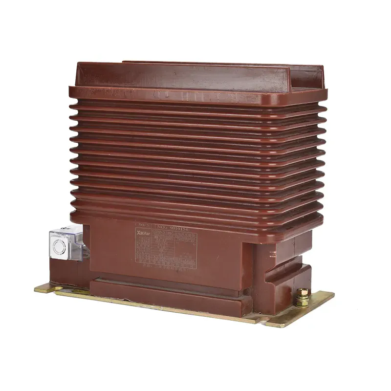
2. What Are the Critical CT Parameters for Protection and Measurement in Renewable Stations?
The selection of a Current Transformer CT for a renewable station depends on three critical parameters: the accuracy class, the burden, and the knee point voltage. For protection applications, the CT must meet the requirements of IEC 60044-1 or IEEE C57.13. For a 100 MW solar farm, the protection CTs are typically class 5P10 or 5P20, which means the CT is accurate to 5 percent at 10 or 20 times the rated current. However, in renewable stations where the fault current is low, a class 5P20 may be unnecessary. A class 5P5 or 5P10 may be more appropriate. The burden is the load presented by the connected relays and wiring. A lower burden allows the CT to achieve the required accuracy. The table below shows the recommended CT parameters for different applications within a renewable station.
| Application | Recommended accuracy class | Typical burden (VA) | Knee point voltage (minimum) | Remarks |
| Inverter output protection | 5P10 (IEC) or C800 (IEEE) | 15 – 30 | 200 V | Must handle inverter fault current limited to 1.5x |
| Station main transformer protection | 5P20 (IEC) or C1000 (IEEE) | 20 – 40 | 400 V | Higher accuracy required for differential protection |
| Revenue metering (export point) | 0.2S (IEC) or 0.15S (IEEE) | 5 – 10 | N/A | Wide range of current from 1% to 120% of rated |
| SCADA monitoring | 1.0 (IEC) or 1.2 (IEEE) | 10 – 20 | N/A | Moderate accuracy, used for display only |
The metering CTs in renewable stations require an accuracy class of 0.2S or better because the station may operate at low output (10 to 20 percent of rated capacity) during partial cloud cover. A standard 0.5 class CT would not be accurate at these low currents. In our factory, we manufacture Current Transformer CT units that are tested for accuracy down to 1 percent of rated current, meeting the 0.2S standard. Our factory uses an automated test system to verify the accuracy at multiple points: 1%, 5%, 20%, 100%, and 120% of rated current.
3. How Does Harmonic Content Affect CT Performance in Renewable Stations?
Inverters produce harmonics, particularly the 3rd, 5th, and 7th orders. These harmonics can cause the CT to saturate prematurely or to generate errors in the secondary current. The CT must have a frequency response that extends to at least the 25th harmonic (1.5 kHz) to accurately reproduce the primary current waveform. In our factory, we test Current Transformer CT units at frequencies up to 2 kHz to ensure they can measure the harmonic content without excessive phase shift. The phase displacement error must be below 1 degree for protection applications and below 0.5 degrees for metering applications. The table below shows the frequency response requirements for different CT classes.
| Application | Frequency range | Maximum phase displacement error | Maximum ratio error |
| Protection (5P class) | 50 Hz – 1.5 kHz | ± 1.0° | ± 5.0% |
| Metering (0.2S class) | 50 Hz – 2.0 kHz | ± 0.5° | ± 0.2% |
| SCADA monitoring (1.0 class) | 50 Hz – 1.0 kHz | ± 2.0° | ± 1.0% |
Wenzhou Xifa Electrical Equipment Co., Ltd. manufactures Current Transformer CT units with a core material that has low hysteresis loss, which improves the frequency response. We have tested our CTs on a 3 MW inverter platform, and the harmonic distortion of the secondary current was within 0.5 percent of the primary current up to the 15th harmonic.
4. What Are the Common CT Selection Mistakes Made in Renewable Projects?
Engineering firms that are experienced in thermal plants often make the same mistakes when they design renewable stations. The first mistake is selecting a CT that is too large. The plant capacity may be 100 MW, but the fault current is limited by the inverter. A CT that is sized for a 50 kA fault current will produce a secondary current that is too low for the relay to measure accurately. The second mistake is selecting a CT with a knee point voltage that is too high. A higher knee point voltage typically means a larger core, which increases the cost and size of the CT. The third mistake is ignoring the impact of the DC component. In a renewable station, the DC component decays in 20 to 30 milliseconds, but it can still cause saturation if the CT is not designed for transient conditions. In our factory, we recommend a CT with a knee point voltage that is at least 1.5 times the required value to accommodate the DC component.
Design recommendation: For a 50 MW solar farm, specify a CT with a rated current of 600 A and a knee point voltage of 300 V. This provides adequate accuracy for both protection and measurement, and it avoids the oversizing that leads to poor performance at low currents.
Frequently Asked Questions About CT Selection for Renewable Stations
Summary for Electrical Design Engineers
The selection of Current Transformer CTs for renewable energy power stations requires a different approach than for conventional thermal plants. The low fault current, the presence of harmonics, and the wide operating range all influence the CT specification. By choosing the correct accuracy class, burden, and knee point voltage, you can ensure accurate measurement and reliable protection. Our factory has supplied CTs to over 200 renewable projects worldwide, and we have developed a selection guide that is specific to inverter-dominated systems.
Wenzhou Xifa Electrical Equipment Co., Ltd. manufactures Current Transformer CT units that are designed for renewable energy applications. We provide a CT selection spreadsheet that calculates the required parameters based on your system voltage, fault current, and burden. Each CT is tested for accuracy at multiple current levels and for transient performance.