

Which Thermoelectric Coolers Are Appropriate for Applications With Limited Installation Space?
2026-10-16
A design engineer is working on a portable medical diagnostic device. The enclosure is 180 mm by 120 mm by 45 mm. The cooling requirement is 15 watts at a temperature difference of 20°C. The available space for the Thermoelectric Coolers and the heat sink is limited to a 40 mm by 40 mm footprint and a height of 25 mm. The engineer cannot use a standard 40 mm TEC module with a tall finned heat sink because the heat sink would exceed the height limit. The engineer must select a TEC with a higher power density and a heat sink with a low profile but high surface area. This guide explains how to select Thermoelectric Coolers for space-constrained applications.
1. What Are the Different Form Factors of Thermoelectric Coolers?
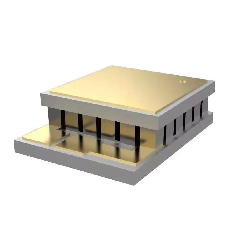
Thermoelectric Coolers are available in three basic form factors: standard square modules, multi-stage modules, and thin-film or micro modules. The standard square module is the most common. It ranges in size from 6 mm by 6 mm to 62 mm by 62 mm. The multi-stage module stacks two or three TECs on top of each other to achieve a larger temperature difference. It is taller than a single-stage module but has a smaller footprint for the same cooling capacity. The thin-film module is only 0.5 to 1.5 mm thick. It is used for cooling small optoelectronic components. The table below compares the form factors.
| Form factor | Typical footprint | Typical height | Maximum temperature difference | Best for limited space |
| Standard single-stage | 10 x 10 to 62 x 62 mm | 3 – 5 mm | 65 – 70°C | Moderate space |
| Multi-stage | 10 x 10 to 30 x 30 mm | 6 – 12 mm | 90 – 120°C | Small footprint, tall |
| Thin-film / micro | 2 x 2 to 10 x 10 mm | 0.5 – 1.5 mm | 40 – 60°C | Very low height |
| Custom shape | Variable | Variable | Depends on design | Unusual geometry |
In our factory, we manufacture Thermoelectric Coolers in standard single-stage, multi-stage, and thin-film configurations. For applications with limited height, the thin-film module is the best choice. For applications with limited footprint, the multi-stage module is the best choice. Fuzhou X-Meritan Technology Co., Ltd. has been manufacturing thermoelectric coolers for over 10 years.
2. How Do You Match the TEC Footprint to the Available Space?
The footprint of the Thermoelectric Coolers must match the available space in the enclosure. If the footprint is too large, the TEC will not fit. If the footprint is too small, the TEC will not provide enough cooling capacity. The cooling capacity is proportional to the number of Peltier couples, which is proportional to the footprint area. The table below shows the cooling capacity for different footprint sizes at a temperature difference of 20°C.
| Footprint | Number of couples | Cooling capacity at ΔT=20°C | Power consumption | Typical application |
| 10 x 10 mm | 31 | 5 W | 8 W | Small sensors, optics |
| 20 x 20 mm | 71 | 15 W | 22 W | Medical diagnostics |
| 30 x 30 mm | 127 | 30 W | 45 W | Portable coolers |
| 40 x 40 mm | 199 | 50 W | 75 W | Compact refrigerators |
| 62 x 62 mm | 397 | 100 W | 150 W | Large enclosures |
The cooling capacity must be matched to the heat load. If the heat load is 15 W and the available footprint is 20 x 20 mm, a TEC with 71 couples is appropriate. If the footprint is limited to 10 x 10 mm, the TEC cannot provide 15 W of cooling at ΔT=20°C. The engineer must either reduce the heat load, increase the available footprint, or accept a lower temperature difference. In our factory, we provide a sizing calculator that helps engineers select the right TEC for their space and cooling requirements.
3. How Does the Heat Sink Design Affect Performance in Limited Space?
The heat sink is the component that rejects the heat from the hot side of the Thermoelectric Coolers. In a space-constrained application, the heat sink must have a low profile but a high surface area. The heat sink performance is characterized by its thermal resistance. A lower thermal resistance means better heat dissipation. The thermal resistance depends on the fin density, the fin height, and the airflow. The table below shows the thermal resistance for different heat sink designs in a 40 x 40 mm footprint.
| Heat sink type | Fin height | Thermal resistance (natural convection) | Thermal resistance (forced convection, 1 m/s) |
| Flat plate | 5 mm | 4.5°C/W | 2.0°C/W |
| Low-profile finned | 10 mm | 2.8°C/W | 1.2°C/W |
| High-density finned | 15 mm | 2.0°C/W | 0.8°C/W |
| Pin fin | 15 mm | 2.2°C/W | 0.9°C/W |
| Vapor chamber | 3 mm | 1.5°C/W | 0.6°C/W |
Design engineer's note: In a 25 mm height limit, the heat sink height is limited to 15 mm, leaving 10 mm for the TEC and the thermal interface material. A high-density finned heat sink with 15 mm fins provides a thermal resistance of 2.0°C/W in natural convection. If the heat load is 22 W, the temperature rise across the heat sink is 44°C. This is too high for most applications. The engineer must use forced convection (a small fan) to reduce the thermal resistance to 0.8°C/W, which gives a temperature rise of 17.6°C. The fan adds height and power consumption but is often necessary in compact designs.
4. What Are the Options for Thermal Interface Materials in Tight Spaces?
The thermal interface material (TIM) is the layer between the TEC and the heat sink, and between the TEC and the cold plate. The TIM fills the microscopic gaps between the surfaces and reduces the thermal resistance. In a tight space, the TIM must be thin and have high thermal conductivity. The table below shows the thermal conductivity and the required thickness for different TIM types.
| TIM type | Thermal conductivity (W/mK) | Typical thickness | Application method |
| Thermal grease | 1 – 8 | 0.05 – 0.1 mm | Screen printing or dispensing |
| Thermal pad | 1 – 6 | 0.5 – 2.0 mm | Manual placement |
| Phase change material | 1 – 3 | 0.1 – 0.2 mm | Manual placement; flows at operating temperature |
| Graphite sheet | 5 – 15 (in-plane) | 0.025 – 0.1 mm | Manual placement |
| Solder | 30 – 50 | 0.05 – 0.1 mm | Reflow soldering |
In our factory, we recommend thermal grease for most compact applications because it provides the lowest thermal resistance at the lowest cost. The grease must be applied in a thin, uniform layer. If the layer is too thick, the thermal resistance increases. For applications with high vibration, a phase change material or a thermal pad may be preferred because they do not pump out or dry. X-Meritan provides thermal interface materials and application guidelines with our Thermoelectric Coolers.
Frequently Asked Questions About Thermoelectric Coolers for Limited Installation Space
Summary for Design Engineers
Selecting Thermoelectric Coolers for applications with limited installation space requires a balance between footprint, height, cooling capacity, and heat sink performance. The thin-film module is the best choice for very low height. The multi-stage module is the best choice for a small footprint. The heat sink must be designed with a low profile but a high surface area, and forced convection is often required. The thermal interface material must be thin and have high thermal conductivity. By matching the TEC and the heat sink to the available space, engineers can achieve reliable cooling in compact enclosures. Fuzhou X-Meritan Technology Co., Ltd. has been manufacturing Thermoelectric Coolers for over 10 years and provides full design support for space-constrained applications.
Fuzhou X-Meritan Technology Co., Ltd. manufactures Thermoelectric Coolers in standard, multi-stage, and thin-film configurations. We provide sizing calculators, heat sink design support, and thermal interface materials for all of our products.