Electrical Protection Guide
Article Summary
Electrical safety is essential in residential, commercial, and industrial distribution systems. Overloads, short circuits, and earth leakage can damage electrical equipment and create serious safety hazards. A Plug in Type RCBO 1P+N combines residual current protection and overcurrent protection in a compact device, helping protect individual electrical circuits while simplifying installation in compatible distribution boards.
However, choosing the right RCBO requires more than checking its rated current. Buyers and electrical professionals must understand its 1P+N configuration, residual operating current, tripping characteristics, breaking capacity, leakage protection type, and plug-in compatibility. This guide explains how the device works, where it is used, which technical specifications matter, and how to evaluate a suitable product for different electrical installations.
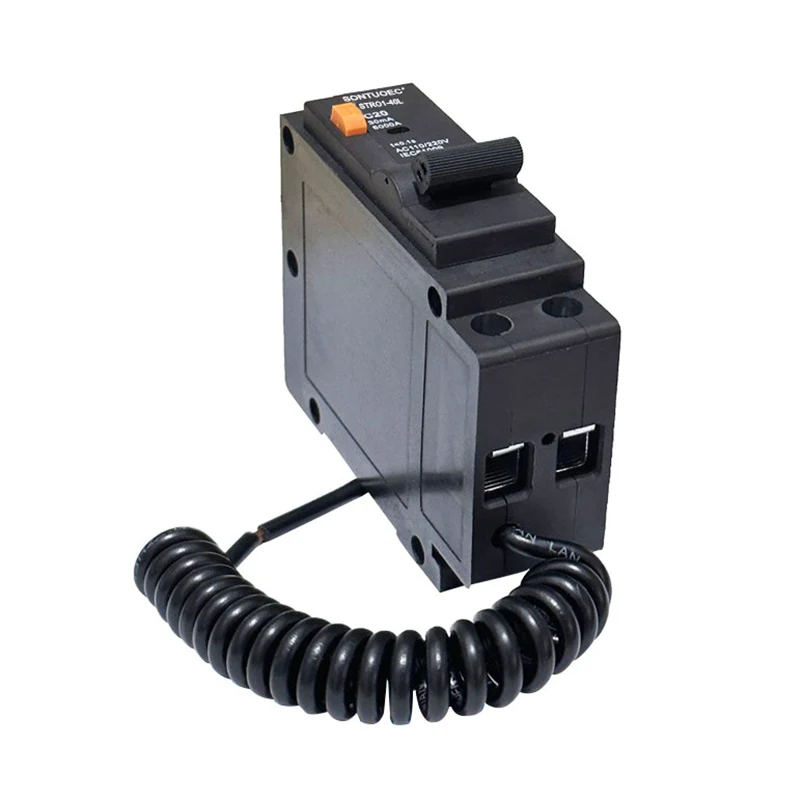
A Plug in Type RCBO 1P+N is an electrical protection device that combines the functions of a miniature circuit breaker (MCB) and a residual current circuit breaker (RCCB). RCBO stands for Residual Current Operated Circuit Breaker with Overcurrent Protection.
The device is designed to provide protection against several electrical faults, including overloads, short circuits, and residual current leakage. Its 1P+N configuration means that it has one phase current path and one neutral current path. In many common designs, the phase pole provides overcurrent protection while the neutral pole is switched but not independently overcurrent-protected. The exact internal configuration should always be confirmed from the manufacturer's product documentation.
The plug-in design refers to its connection and mounting arrangement. Instead of relying entirely on conventional screw connections for mounting, the device uses a compatible plug-in connection system or base. Depending on the product design, the plug-in connection may be on the supply side, while the outgoing circuit conductors connect through separate terminals.
Single-phase electrical systems commonly use a live conductor and a neutral conductor. A 1P+N RCBO is designed to work with both current paths, allowing the device to disconnect the associated circuit according to its specified switching arrangement.
This configuration is useful for individual outgoing circuits in compatible distribution boards. It can also help simplify circuit-level protection in installations where separate protection is preferred for lighting, sockets, and dedicated appliances.
A Plug in Type RCBO 1P+N combines two main protective functions within one device. Each function responds to a different type of electrical fault.
An overload occurs when a circuit carries more current than its intended operating capacity for a sufficient period. This may happen when too many appliances are connected to one circuit or when equipment draws excessive current during operation.
The thermal protection mechanism responds to prolonged overcurrent. When the current exceeds the device's rated operating conditions, the mechanism eventually trips and disconnects the circuit to help prevent excessive heating of cables and electrical components.
A short circuit occurs when conductors with different electrical potentials become unintentionally connected through a low-impedance path. The resulting fault current can rise rapidly to a dangerous level.
The magnetic tripping mechanism detects sufficiently high fault currents and operates quickly to interrupt the circuit. The device's rated breaking capacity must be suitable for the prospective short-circuit current at the installation point.
Residual current protection monitors the current flowing through the live and neutral conductors. Under normal conditions, the current entering the circuit should correspond to the current returning through the associated conductors.
If some current escapes through an unintended path, such as damaged insulation or an electrical connection to earth, the device detects the resulting imbalance. When the residual current reaches the specified operating threshold under the required test conditions, the RCBO trips.
Combining these functions can reduce the number of separate devices required for an individual outgoing circuit. It also makes it easier to identify which protected circuit has experienced a fault.
Plug-in Type RCBOs are designed to meet the practical needs of electrical distribution systems where installation efficiency, circuit protection, and equipment organization are important.
The plug-in connection system can simplify device mounting in distribution boards specifically designed for the corresponding product. It may reduce the amount of conventional wiring work required at the plug-in interface.
However, plug-in devices must always be used with their approved compatible bases or panel systems. Similar-looking products from different manufacturers are not automatically interchangeable.
A dedicated RCBO can protect an individual outgoing circuit. If one circuit develops an earth leakage or overcurrent fault, the corresponding protective device can disconnect that circuit rather than relying on one common residual current device to protect multiple outgoing circuits.
Combining residual current and overcurrent protection in one device can help simplify distribution board layouts. This is particularly useful in applications where multiple single-phase circuits need independent protection.
When individual circuits have dedicated RCBOs, maintenance personnel can more easily identify the circuit associated with a trip event. This can reduce troubleshooting time, although proper fault diagnosis is still necessary.
Different RCBO models may offer different rated currents, residual operating currents, tripping curves, breaking capacities, and residual current detection types. This allows electrical designers to specify a device according to the characteristics of the protected circuit.
Technical specifications determine whether a Plug in Type RCBO 1P+N is suitable for a particular electrical system. Buyers should understand the following parameters before requesting a quotation or confirming an order.
|
Specification
|
Meaning
|
Selection Consideration
|
|
Pole Configuration
|
1P+N phase and neutral current paths.
|
Confirm compatibility with the electrical system and required neutral switching.
|
|
Rated Current (In)
|
Current rating of the device under specified conditions.
|
Must be coordinated with cable capacity and circuit load.
|
|
Rated Voltage (Ue)
|
Operational voltage for which the device is designed.
|
Must match the supply system.
|
|
Residual Current (IΔn)
|
Rated residual operating current.
|
Selected according to protection objectives and applicable regulations.
|
|
Tripping Curve
|
Defines the overcurrent tripping characteristics.
|
Consider circuit inrush current and load characteristics.
|
|
Breaking Capacity
|
Maximum specified short-circuit current the device can safely interrupt under its rating conditions.
|
Must meet or exceed the required installation fault level, with proper coordination.
|
|
Residual Current Type
|
Describes the forms of residual current the device can detect.
|
Match the electronic characteristics of connected loads.
|
|
Mounting System
|
Defines the plug-in base and connection arrangement.
|
Must match the approved distribution board system.
|
Common RCBO current ratings may include 6A, 10A, 16A, 20A, 25A, 32A, 40A, and other values depending on the product range.
A higher rated current does not automatically mean better protection. The selected rating must be coordinated with conductor size, installation method, expected load, and applicable electrical design requirements.
Common residual current ratings include 10mA, 30mA, 100mA, and 300mA, depending on the device and intended application.
A 30mA device is commonly used for additional protection against electric shock in many final-circuit applications, subject to local regulations. Higher residual current ratings may be used for other protective or fire-risk reduction purposes where the system design permits.
Breaking capacity is commonly expressed in kiloamperes (kA). For example, a product may be rated at 4.5kA, 6kA, or 10kA. These values represent specified short-circuit interruption capabilities, not the normal operating current of the circuit.
Choosing an insufficient breaking capacity may compromise the safety of the installation. The available fault current and coordination requirements must be evaluated by a qualified electrical designer.
Plug-in Type RCBO 1P+N devices are commonly considered for single-phase distribution systems that require independent circuit protection.
In residential buildings, individual RCBOs can protect lighting circuits, socket circuits, kitchen appliances, and other dedicated electrical loads. Separate protection can help prevent a fault in one circuit from unnecessarily interrupting other circuits.
Offices, retail stores, hotels, and commercial properties use distribution boards to supply different areas and equipment. A dedicated RCBO for selected outgoing circuits can make circuit protection and fault identification more manageable.
Some industrial installations require single-phase protection for control panels, auxiliary power supplies, lighting, and other compatible circuits. The device must be selected according to the actual load and environmental conditions.
Plug-in RCBOs are particularly relevant to distribution systems designed around compatible plug-in mounting arrangements. They can help simplify panel assembly and support standardized circuit protection layouts.
Panel builders and electrical equipment manufacturers may incorporate plug-in RCBOs into suitable distribution assemblies. Consistent product dimensions, terminal arrangements, and technical documentation are important for repeatable production and quality control.
Choosing an RCBO requires a complete understanding of the electrical circuit. Focusing on one specification while ignoring the others may result in nuisance tripping, inadequate protection, or installation incompatibility.
Identify the nominal voltage, frequency, earthing arrangement, and single-phase circuit configuration. Confirm that the selected 1P+N device is designed for the intended supply system.
Determine the expected operating current based on the connected equipment and installation conditions. The RCBO rating must be coordinated with the conductor's current-carrying capacity and the circuit's protective requirements.
B-type and C-type curves are commonly used in many low-voltage applications, while D-type devices may be considered for particular loads with higher inrush currents. The correct curve depends on the load characteristics and fault-loop conditions.
|
Curve
|
Typical Magnetic Tripping Range
|
General Considerations
|
|
B
|
3–5 × In
|
Often used for circuits with relatively low inrush currents.
|
|
C
|
5–10 × In
|
Commonly considered for general circuits with moderate inrush currents.
|
|
D
|
10–20 × In
|
May be suitable for selected loads with high starting currents.
|
These are commonly referenced magnetic operating ranges. Actual trip performance must be checked against the specific product's standard and manufacturer data.
Different electrical loads can generate different residual current waveforms. A basic AC-type device may not be suitable for every installation, particularly where electronic power conversion equipment is involved.
Calculate or obtain the prospective short-circuit current at the installation point. Select a device with an adequate rated breaking capacity and coordinate it with upstream protection.
Check the exact mounting base, contact arrangement, dimensions, terminal orientation, and approved panel series. This is essential because plug-in connection systems are not universally standardized across all brands and product families.
Residual current protection types describe the forms of residual current that an RCBO is designed to detect. Selecting the appropriate type is particularly important in modern electrical systems containing electronic equipment.
Type AC devices are designed to detect sinusoidal alternating residual currents. Their suitability depends on the electrical loads and the protection requirements of the installation.
Type A devices detect sinusoidal alternating residual currents and pulsating direct residual currents. They are commonly considered for circuits supplying equipment with electronic components, such as certain household appliances and electronic power supplies.
Type F devices are designed for additional residual current waveform conditions associated with certain frequency-controlled equipment, including some single-phase variable-speed drives. Their application should be verified against the load manufacturer's recommendations.
Type B devices provide detection of a broader range of residual current waveforms, including smooth direct residual current, within their specified operating conditions. They may be required for certain power electronic systems, charging equipment, and industrial applications.
Correct installation is essential for reliable RCBO operation. Although a plug-in arrangement can simplify mounting, it does not eliminate the need for professional electrical installation and verification.
Installation must be carried out by a qualified electrician using the manufacturer's approved procedures. The supply must be isolated and verified as de-energized before any work begins.
The device must be seated correctly in its designated base, and all required connections must be secured according to the specified installation method. Improper alignment or incomplete engagement can create poor electrical contact and excessive heating.
Appropriate electrical tests should be performed before energizing the circuit. Depending on the installation and applicable regulations, these may include insulation resistance, continuity, polarity, earth fault loop impedance, and residual current device operation tests.
The built-in test button should also be checked according to the manufacturer's instructions. However, the test button alone does not replace complete installation verification.
Unexpected tripping does not necessarily indicate that an RCBO is defective. It may be responding correctly to an electrical fault. Identifying the underlying cause is important before replacing the device.
|
Problem
|
Possible Cause
|
Recommended Investigation
|
|
Frequent Tripping
|
Earth leakage, overload, or faulty appliances.
|
Have a qualified electrician isolate and test the affected circuit.
|
|
Failure to Reset
|
Persistent fault, incorrect installation, or damaged mechanism.
|
Check the circuit and device according to manufacturer procedures.
|
|
Unexpected Operation
|
Transient leakage or unsuitable residual current type.
|
Evaluate the load characteristics and leakage current.
|
|
Device Overheating
|
Loose connections, excessive current, or poor plug-in contact.
|
Isolate the supply and inspect the connection system professionally.
|
|
Test Button Does Not Operate
|
Supply issue, incorrect wiring, or device failure.
|
Check the supply and installation against the manufacturer's instructions.
|
|
Intermittent Power Loss
|
Loose connections, circuit faults, or unstable supply.
|
Inspect the installation and measure electrical conditions.
|
Repeatedly resetting an RCBO without investigating the cause can expose people and equipment to unnecessary risks. If the device continues to trip, the circuit should be inspected by a qualified electrician.
RCBOs, MCBs, and RCCBs are all used in low-voltage electrical protection systems, but their functions are different. Understanding these differences helps buyers select an appropriate protective arrangement.
|
Device
|
Overload Protection
|
Short-Circuit Protection
|
Residual Current Protection
|
|
MCB
|
Yes
|
Yes
|
No
|
|
RCCB
|
No
|
No
|
Yes
|
|
RCBO
|
Yes
|
Yes
|
Yes
|
An MCB provides overcurrent protection but does not detect residual current leakage. An RCCB provides residual current protection but generally requires separate overcurrent protection.
An RCBO integrates both functions into one device. This makes it particularly useful when individual circuits require combined protection and a compact distribution board arrangement is preferred.
For larger installations, the final protection architecture should consider selectivity, backup protection, fault levels, circuit grouping, and the applicable electrical standards.
For electrical wholesalers, distributors, panel manufacturers, and project contractors, selecting a reliable supplier is just as important as choosing the correct technical specifications.
Check whether the product is designed and tested according to the relevant requirements of IEC 61009-1 and other applicable standards. Confirm the actual test reports, certificates, and conformity documentation for the specific model rather than relying on general company claims.
Important quality considerations include contact performance, thermal and magnetic tripping characteristics, insulation properties, mechanical durability, and reliability of the plug-in connection.
A professional manufacturer should provide clear product specifications, wiring diagrams, dimensions, rated parameters, installation instructions, and applicable compliance documents.
For distributors and OEM customers, consistent production capacity, product configuration options, packaging requirements, and delivery arrangements are important factors when establishing a long-term supply relationship.
Clear communication about product selection, compatibility, and application requirements can help reduce purchasing mistakes and installation problems.
A Plug in Type RCBO 1P+N is a practical solution for single-phase electrical distribution systems that require combined overload, short-circuit, and residual current protection. Its integrated design can simplify circuit protection arrangements, while the plug-in connection system supports convenient mounting in compatible distribution boards.
However, reliable protection depends on more than the device's physical design. Rated current, residual operating current, tripping characteristics, breaking capacity, residual current detection type, and plug-in compatibility must all be carefully evaluated.
For electrical contractors, panel builders, distributors, and equipment manufacturers, working with a qualified electrical protection device supplier helps ensure that product specifications match the requirements of the intended application.