

A Micro Switch may occupy only a small space inside a machine, yet its switching point can determine whether a mechanism stops at the right position, whether a door is correctly detected, or whether a control signal is delivered at the required moment. For equipment designers, maintenance teams and component buyers, the challenge is rarely finding a switch that physically fits. The harder task is matching the switch to the actual mechanical movement, electrical load, operating environment and expected service life. This guide explains the key factors behind Micro Switch selection and application, with practical details that can help reduce premature contact failure, inconsistent actuation and installation problems.
What a Micro Switch Does
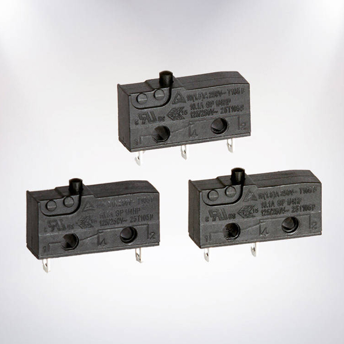
A Micro Switch is a compact electromechanical switch designed to change the state of its contacts when a mechanical actuator reaches a defined position. It is commonly associated with snap-action switching, where the internal contact movement occurs rapidly rather than following the actuator movement slowly and continuously. This characteristic gives the switch a clearly defined operating point and makes it useful for position detection, limit sensing, interlocking and control functions.
Depending on the design, a Micro Switch may provide normally open (NO), normally closed (NC) and common (COM) terminals. This allows one compact component to perform different switching functions within a machine. The same basic principle can therefore be applied to equipment doors, control mechanisms, moving assemblies, counters, appliances, automation equipment and many other systems.
How the Snap-Action Mechanism Works
The defining feature of a typical Micro Switch is the snap-action mechanism. When external force is applied to the actuator, an internal spring mechanism stores and redirects that force. Once the operating point is reached, the movable contact rapidly transfers from one electrical position to another.
Because the switching movement is generated by the internal mechanism, the contact transition is not simply a slow copy of the operator's movement. This helps create a repeatable switching point even when the external actuator is moved at different speeds. Technical references from Omron and ZF describe snap-action switches in terms of defined operating force, travel and rapid contact movement.
For machine designers, this matters because the mechanical cam, lever or moving component must be positioned around the switch's actual operating point rather than merely pressing the actuator until it feels fully depressed. Pre-travel, operating position, release position, differential travel and over-travel all affect the way the switch behaves inside the finished mechanism.
| Term | Meaning | Why It Matters |
|---|---|---|
| Operating Force | Force needed to move the actuator to the operating point. | Determines how much mechanical force the machine must provide. |
| Pre-travel | Actuator movement before the contacts switch. | Helps determine the position at which the electrical signal changes. |
| Over-travel | Permitted actuator movement after the operating point. | Provides mechanical tolerance and helps prevent excessive loading. |
| Release Point | Position where the contacts return after the actuator moves back. | Important when repeatable ON/OFF positioning is required. |
| Differential Travel | Difference between operating and release positions. | Helps prevent unwanted repeated switching near the threshold. |
Which Components Matter Inside the Switch
A compact enclosure does not mean a simple internal structure. A typical Micro Switch contains a housing, actuator, spring mechanism, movable contact, fixed contacts and terminals. The precise construction varies by series and application.
The external part receives mechanical movement. Plunger, lever and roller configurations are commonly available, allowing the same switching principle to accommodate different machine geometries.
The spring and snap mechanism determine how the actuator movement is converted into rapid contact movement.
Contact material and geometry influence electrical switching performance, contact resistance and suitability for particular loads.
The housing protects the internal mechanism while the terminal design determines how the switch connects to the equipment wiring.
Contact material deserves particular attention when the switch handles low-level signals or repeated electrical loads. A switch designed for power switching should not automatically be assumed to be ideal for every signal-level application. Likewise, a model intended for a low-energy control circuit should not be substituted into a higher-current application simply because the body dimensions are identical.
Which Actuator Matches the Machine Movement
Actuator selection is one of the most practical decisions when specifying a Micro Switch. The switch must not only fit the available mounting space; its actuator needs to interact naturally with the moving component.
Plunger Actuators
A plunger is suitable when the machine can provide relatively direct linear movement. It is often used where a cam, door, slider or mechanical stop approaches the switch along a controlled path.
Lever Actuators
A lever provides additional mechanical reach and can accommodate movement that is not perfectly aligned with a short plunger. Different lever lengths can change the force and travel experienced at the actuator, so the switch datasheet should be checked rather than assuming that a longer lever is always preferable.
Roller Actuators
A roller can reduce sliding friction when a moving surface passes across the actuator. This can be useful for moving mechanisms, cams and position-detection applications where the actuator is contacted repeatedly.
TE Connectivity identifies plunger, straight or formed lever, and roller configurations among common snap-action switch actuator styles.
Which Electrical Specifications Need Attention
Electrical rating is one of the most frequently misunderstood parts of Micro Switch selection. A rating printed on a product label is not a universal indication that the switch can handle every type of load at that current.
Voltage, current, AC or DC operation and load type all need to be considered. Motor, solenoid, lamp and capacitive loads may produce different electrical stresses from a simple resistive load. DC switching can also require particular attention because the arc does not extinguish in exactly the same way as an AC arc.
| Electrical Item | What to Confirm | Typical Buyer Question |
|---|---|---|
| Rated Voltage | Maximum applicable AC or DC voltage for the specified load condition. | Does the rating match my circuit voltage? |
| Rated Current | Permitted switching current under the specified test/load conditions. | Is the actual load below the specified rating? |
| Load Type | Resistive, inductive, motor, lamp or electronic load. | Will startup or inrush current affect contact life? |
| Contact Configuration | SPST, SPDT or another specified arrangement. | Which terminal should be open or closed before actuation? |
| Contact Material | Material and construction suited to the intended signal or power level. | Is the switch being used for power or low-level sensing? |
Manufacturer specifications demonstrate how widely these values can vary. For example, Honeywell's Micro Switch product families include models ranging from subminiature devices to larger basic switches, with different current ratings, actuator arrangements and service-life specifications.
For this reason, purchasing should be based on the complete part specification rather than a generic phrase such as "10A Micro Switch." If the switch controls a motor, heater, solenoid or other inductive load, provide the supplier with the real operating conditions before finalizing the model.
Which Environmental Conditions Affect Reliability
A Micro Switch installed in a clean indoor control panel faces very different conditions from one installed near dust, moisture, vibration or temperature fluctuations. Environmental requirements should therefore be established before the switch is selected.
- Dust: Fine particles can affect exposed mechanical areas and contact reliability.
- Moisture: Humidity and water exposure may require an appropriately sealed construction.
- Temperature: Housing materials, contact materials and spring characteristics must remain suitable across the operating range.
- Vibration: The mounting method and switch construction should be suitable for the machine's vibration level.
- Mechanical shock: Equipment subjected to repeated impact may require a switch specifically designed for higher shock resistance.
- Contaminants: Oil, chemicals and manufacturing debris can influence material compatibility and service life.
There is no single environmental specification that makes a switch suitable for every industrial application. A sealed Micro Switch may be preferable for one installation, while a compact unsealed model may be entirely adequate inside a protected enclosure.
Where Micro Switches Are Commonly Used
The small size and clearly defined switching action of Micro Switches make them useful in equipment where a physical movement needs to become an electrical signal. Their applications range from everyday appliances to industrial automation.
Door detection, position confirmation, control functions and interlocking mechanisms in equipment such as washing machines, refrigerators and other appliances.
End-of-travel detection, machine position feedback, counters and mechanical control sequences.
Limit detection and position confirmation where compact mechanical sensing is required.
Paper-path detection, buttons, covers, doors and other moving mechanisms.
Door, cover and tamper-position detection in suitable low-power control circuits.
Mechanical status feedback where a defined switching position is more practical than an electronic sensor.
Industry references list applications including appliance doors, vending equipment, office machines, medical equipment, security equipment and computer peripherals.
Which Details Should Be Confirmed Before Ordering
A buyer can avoid many compatibility problems by preparing the mechanical and electrical requirements before sending an inquiry. Physical dimensions alone are not enough because two switches with similar bodies may have significantly different operating forces, terminals, contact configurations or electrical ratings.
- Confirm the required switch body dimensions and mounting-hole pattern.
- Define the required actuator style: plunger, lever, roller or another configuration.
- Measure the available machine travel and identify the actual operating position.
- Check the required operating force and whether the machine can reliably actuate the switch.
- Confirm pre-travel, over-travel and differential travel against the mechanical movement.
- Specify the required contact configuration, such as SPST or SPDT.
- Provide the actual voltage, current and load type.
- Consider inrush current for motors, lamps, solenoids and similar loads.
- Specify the required operating temperature and environmental conditions.
- Confirm the expected mechanical and electrical service life.
- Check terminal type and available wiring space.
- Request a drawing or datasheet when dimensional compatibility is critical.
A Practical Specification Checklist
| Requirement | Information to Prepare |
|---|---|
| Application | Machine, appliance, control panel, automation equipment or other end use |
| Actuation | Plunger, lever, roller or customized actuator |
| Electrical Load | Voltage, current, AC/DC and load characteristics |
| Contact Logic | NO, NC, COM or required pole/throw configuration |
| Installation | Mounting dimensions, terminal style and available space |
| Environment | Temperature, humidity, dust, water, vibration and other exposure |
| Quantity | Prototype, trial order, regular production or OEM volume |
Common Micro Switch Selection and Installation Problems
Choosing by Size Alone
A switch may fit the mounting position while still having the wrong electrical or mechanical characteristics. Body dimensions should be only the starting point.
Ignoring DC Ratings
A switch carrying a particular AC rating should not automatically be treated as having the same DC switching capability. Always check the manufacturer's specified DC rating when switching batteries, motors or other DC loads.
Using Excessive Actuator Force
The machine mechanism should activate the switch within its specified operating range. Forcing the actuator beyond its permitted movement can create unnecessary mechanical stress.
Forgetting Inrush Current
A motor may draw considerably more current during startup than during steady operation. The steady-state current alone may therefore provide an incomplete picture of the switching duty.
Mounting the Switch as a Mechanical Stop
The switch should detect the machine position rather than absorb the machine's full stopping force. A properly designed cam or stop should control the mechanical movement.
Replacing a Model Without Checking the Datasheet
Two visually similar Micro Switches can differ in terminal arrangement, operating force, actuator travel and contact rating. A direct replacement should therefore be checked against the original technical requirements.
Micro Switch FAQ
A Micro Switch is a compact electromechanical switch that commonly uses a snap-action mechanism to change contact state at a defined actuator position. It is widely used for position detection, limit sensing, interlocking and control functions.
Not exactly. A Micro Switch describes a compact snap-action switching mechanism, while a limit switch generally describes a device used to detect the position or movement limit of machinery. A Micro Switch can be used as the switching element inside a position-detection assembly.
NO means normally open, NC means normally closed, and COM means common. In a typical SPDT arrangement, the common terminal changes connection between the normally closed and normally open contacts when the switch is actuated.
Some Micro Switch models can switch motor-related loads, but the correct model depends on motor voltage, operating current, starting or inrush current and the manufacturer's specified load rating. The AC or DC rating must also be checked.
Service life varies substantially by model and application. Mechanical life and electrical life are different specifications, and electrical load, actuator movement and environmental conditions can all affect actual service life. Manufacturer data should be used for the specific model rather than relying on a generic cycle count. Honeywell, for example, publishes different life figures across its Micro Switch families.
Start with the movement of the machine. A plunger suits direct linear movement, while a lever or roller can accommodate different approach directions and mechanical geometries. The actuator's operating force and travel should then be matched with the machine.
Some models are rated for both, but the permitted voltage and current may differ between AC and DC. Never assume that an AC rating can be transferred directly to a DC circuit.
Provide the application, switch dimensions, actuator type, electrical voltage and current, AC/DC requirement, contact configuration, operating travel, environmental conditions, quantity and any required certifications or approvals. A product drawing or existing switch model number is especially useful for replacement projects.
Making a Micro Switch Specification Easier to Verify
The most reliable purchasing process begins with the actual operating conditions rather than a generic product name. A well-defined specification connects the machine movement with the actuator, the actuator with the snap-action mechanism, and the electrical load with the appropriate contact system.
For OEM equipment, this approach can also make future replacement easier. Keeping the switch drawing, terminal arrangement, electrical rating, actuator dimensions and application requirements in the product documentation gives maintenance teams a clear reference when the machine enters long-term service.
WEIPENG can support Micro Switch sourcing and application discussions based on your equipment requirements. Whether you are developing a new product, replacing an existing switch or purchasing components for regular production, providing the key mechanical and electrical parameters at the inquiry stage can help shorten the specification process.
Need a Micro Switch for Your Application?
Tell WEIPENG your required actuator type, mounting dimensions, voltage, current, contact configuration and application conditions. Our team can review the requirements and help match the Micro Switch specification to your equipment.
For OEM projects, replacement requirements or bulk purchasing, contact us with your drawings or existing switch model and let us discuss the suitable configuration for your application.
Contact Us