

What thickness is standard for a Converter and Selector PCB
2026-10-15
Aisen is a high-precision PCB manufacturer with 21 years of experience serving industrial control, audio processing and signal conversion system clients, and its Converter and Selector PCB products are widely recognized for stable signal integrity and long-term operational reliability across multi-channel signal switching and analog-to-digital conversion scenarios. As a core carrier for signal routing, level conversion and channel selection circuits, the thickness of this type of PCB directly affects mechanical stability, signal transmission performance and compatibility with standard enclosure assembly. This article breaks down verified industry standards, practical application data and design guidelines to help hardware engineers select the most suitable thickness specification for their projects.
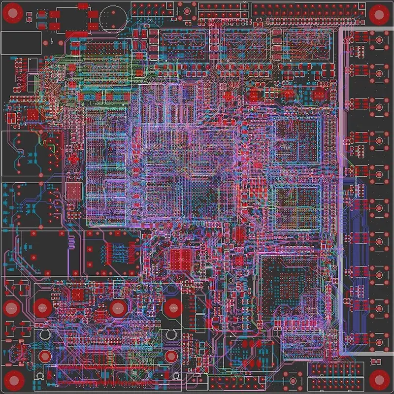
Standard Thickness Specifications and Application Scenarios
The Converter and Selector PCB follows widely accepted IPC-6012 PCB manufacturing standards, with three mainstream thickness grades covering nearly all common application demands. The table below lists their key parameters and typical use cases:
| Standard Thickness | Copper Foil Weight | Typical Application Scenario | Mechanical Stability Rating |
|---|---|---|---|
| 1.0mm | 1oz | Small low-signal audio selector modules | Good for low-load compact devices |
| 1.6mm | 1oz / 2oz | Industrial multi-channel signal converter boards | Excellent for most general use cases |
| 2.0mm | 2oz / 3oz | High-current industrial signal switching systems | Maximum rigidity for heavy load setups |
Core Thickness Design Principles
- General industrial default standard: The 1.6mm thickness Converter and Selector PCB is the most widely adopted industry default, perfectly matching standard DIN rail mounting enclosures, common connector pin lengths and automated assembly equipment processes.
- High-density compact design selection: For small consumer audio or portable test equipment, the 1.0mm thickness version reduces overall device weight and fits ultra-thin enclosure design requirements without sacrificing basic signal stability.
- High-current heavy load selection: For industrial signal conversion systems with power traces carrying more than 5A current, the 2.0mm thickness Converter and Selector PCB provides larger trace routing space and better heat dissipation performance, avoiding overheating risks under continuous full load operation.
- Special customization support: For scenarios with special installation space constraints or shock and vibration requirements, customized thickness specifications ranging from 0.8mm to 3.2mm are also available to meet unique project demands.
Converter and Selector PCB FAQ
Q: What performance risks will occur if I use a non-standard 0.8mm ultra-thin board for an industrial multi-channel signal switching project?
A: Ultra-thin boards lack sufficient mechanical rigidity, which may cause board bending during wave soldering or long-term field operation. This can crack signal traces, loosen connector pins and introduce unexpected signal crosstalk between adjacent high-speed conversion channels, leading to unstable signal output.
Q: Does the 1.6mm standard Converter and Selector PCB support 4-layer high-speed signal routing for analog-to-digital conversion applications?
A: Yes. The 1.6mm thickness provides enough internal space to arrange independent power plane, ground plane and two signal layers, which effectively isolates high-speed digital conversion signals from low-level analog selection signals, ensuring the signal integrity required for high-precision conversion.
Q: For a rack-mounted 16-channel signal selector system that needs to be inserted and extracted frequently, which thickness specification is the most appropriate choice?
A: The 2.0mm thickness Converter and Selector PCB is the optimal option. Its higher mechanical rigidity can withstand repeated plugging and unplugging forces without board deformation, and it can maintain long-term stable contact between edge connectors and the backplane, avoiding intermittent signal disconnection issues.
As a specialized PCB manufacturer focused on signal processing board solutions, Aisen provides every Converter and Selector PCB with full IPC-6012 compliance testing reports, strict thickness tolerance control within ±0.1mm and 100% electrical continuity inspection. Contact us today to send your schematic, application scenario and thickness requirement details, and our engineering team will provide a free customized PCB design review, optimized thickness recommendation and competitive production quotation to perfectly match your project’s performance and assembly needs.