

What testing methods ensure the quality of Sensor PCBA for automotive applications
2026-05-27
The reliability of Sensor PCBA in modern vehicles directly affects safety systems, engine control, and driver assistance features. Unixplore Electronics specializes in automotive-grade Sensor PCBA manufacturing, where rigorous testing is not optional but mandatory. Automotive electronics must endure extreme temperatures, vibration, moisture, and electromagnetic interference. This article explores the essential testing methods that guarantee the highest quality for Sensor PCBA used in automotive applications.
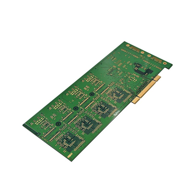
Core Testing Methods for Automotive Sensor PCBA
| Testing Method | Purpose | Automotive Standard |
|---|---|---|
| In-Circuit Testing (ICT) | Detects short circuits, open circuits, and component placement errors | ISO 9001 |
| Flying Probe Testing | Verifies electrical performance without custom fixtures | IATF 16949 |
| Thermal Cycling Test | Simulates extreme temperature changes from -40°C to 125°C | AEC-Q100 |
| Vibration & Mechanical Shock Test | Ensures solder joint integrity under road conditions | ISO 16750-3 |
| Humidity & Salt Spray Test | Assesses corrosion resistance in harsh environments | IEC 60068-2-52 |
| Electromagnetic Compatibility (EMC) Test | Checks immunity to and emission of electrical noise | CISPR 25 |
| Boundary Scan (JTAG) | Tests interconnections on high-density Sensor PCBA | IEEE 1149.1 |
Why Each Test Matters for Automotive Safety
-
In-Circuit Testing catches manufacturing defects early. A single missing resistor on a Sensor PCBA can cause airbag deployment failure. ICT verifies each component's presence and value.
-
Thermal Cycling replicates under-hood conditions. A Sensor PCBA controlling engine timing must survive thousands of hot-cold cycles without cracking solder joints.
-
Vibration Testing mimics potholes and rough roads. Loose connectors or fractured traces on a wheel speed Sensor PCBA could disable anti-lock braking systems.
-
EMC Testing ensures nearby motors or radios do not corrupt sensor signals. A Sensor PCBA for lidar must ignore electromagnetic noise from windshield wipers.
Sensor PCBA FAQ – Common Questions
Question 1: How often should automotive Sensor PCBA be retested during mass production?
Answer: For high-volume automotive production, Unixplore Electronics recommends 100% In-Circuit Testing on every Sensor PCBA plus batch sampling for environmental tests. Typically, 1 in every 500 units undergoes full thermal and vibration testing. Additionally, first-off and last-off units from each shift are subjected to EMC and humidity testing. This layered strategy catches both random and drift defects. Compliance with IATF 16949 requires documented traceability linking each Sensor PCBA to its test results.
Question 2: What is the most common hidden defect found in automotive Sensor PCBA testing?
Answer: Head-in-pillow solder joints are the most frequent hidden defect. This occurs when a ball grid array component's solder ball does not fully wet the pad, creating an intermittent connection. Standard visual inspection misses it. However, combined thermal cycling and continuity testing reveals it when the Sensor PCBA heats up and the joint temporarily separates. Unixplore Electronics uses automated X-ray inspection (AXI) alongside boundary scan to detect head-in-pillow defects before thermal testing, eliminating false passes.
Question 3: Can a Sensor PCBA that passes all electrical tests still fail in a car environment?
Answer: Yes. Electrical tests alone cannot predict mechanical or chemical failures. A Sensor PCBA might pass all functional checks at room temperature but fail after 500 hours of salt spray exposure, leading to trace corrosion. Similarly, micro-vibrations from the engine can gradually wear through poorly plated vias. That is why Unixplore Electronics always combines electrical, mechanical, and environmental stress tests. Only a Sensor PCBA that survives thermal shock, vibration, and humidity while maintaining electrical performance is truly automotive-grade.
Best Practices from Unixplore Electronics
Unixplore Electronics implements a zero-defect philosophy for every Sensor PCBA. Key practices include:
-
Design for Testability (DFT) added at schematic stage
-
Automated optical inspection (AOI) after solder paste and reflow
-
Real-time statistical process control (SPC) on test equipment
-
Traceability with unique serial numbers per Sensor PCBA
Contact Us
Ensure your next vehicle program uses the most reliable Sensor PCBA on the market. Unixplore Electronics provides full test coverage from ICT to EMC and thermal cycling, all documented to IATF 16949. Contact our engineering team today for a free design review and test plan consultation.