

What Makes Cycling Thermoelectric Coolers Reliable in High-Frequency Switching?
2026-09-23
In many precision thermal management applications, the Cycling Thermoelectric Coolers must switch between heating and cooling modes hundreds of times per day. This is not the steady-state operation that most TE cooler datasheets describe. Each switch cycle imposes a thermal transient on the module: the ceramic substrates expand and contract, the solder joints experience shear stress, and the thermoelectric pellets undergo rapid temperature changes. Over 100,000 cycles, these stresses can cause solder cracking, pellet fracture, or delamination. The reliability of a cycling TE cooler in high-frequency switching is determined by three factors: the solder material, the module construction, and the control strategy. This guide explains each factor and how to validate reliability through accelerated life testing.
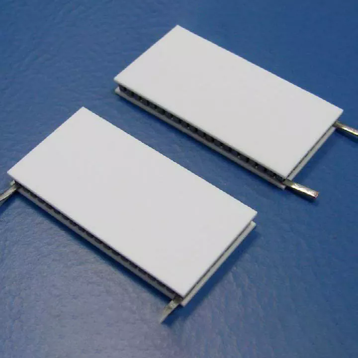
1. Why Does Solder Fatigue Limit the Life of a Cycling Thermoelectric Cooler?
The solder joints in a thermoelectric module connect the thermoelectric pellets to the ceramic substrates. These joints must conduct both electricity and heat. When the module switches between heating and cooling, the temperature of the solder joint changes by 40°C to 80°C within seconds. This temperature swing causes the solder to expand and contract. Because the solder is constrained between the pellet and the ceramic, the expansion and contraction create shear strain. Over many cycles, the shear strain causes fatigue cracking. The rate of fatigue cracking depends on the solder composition, the joint thickness, and the temperature swing. The table below compares the fatigue life of common solder materials used in thermoelectric modules.
| Solder material | Melting point (°C) | Thermal fatigue life (cycles) | Typical application |
| SnPb (63/37) | 183 | 50,000 – 100,000 | Standard TE modules |
| SnSb (95/5) | 235 | 100,000 – 200,000 | High-temperature TE modules |
| SnAgCu (SAC305) | 217 | 150,000 – 300,000 | High-reliability applications |
| Diffusion-bonded (no solder) | N/A | > 500,000 | Extreme cycling applications |
In our factory, we use SnAgCu solder for our Cycling Thermoelectric Coolers that are designed for high-frequency switching. The SAC305 alloy has a higher melting point and better fatigue resistance than SnPb. We also control the solder joint thickness to 50 to 80 microns, which is the optimal range for fatigue life. A thicker joint reduces the shear strain per cycle but increases the thermal resistance.
2. How Does Module Construction Affect Cycling Reliability?
The construction of the thermoelectric module affects its ability to withstand thermal cycling. There are four key construction features. The first is the ceramic substrate material. Alumina (Al2O3) is the standard, but aluminum nitride (AlN) has higher thermal conductivity and better thermal shock resistance. The second is the pellet geometry. Taller pellets have higher thermal resistance but lower shear strain. Shorter pellets have lower thermal resistance but higher shear strain. The third is the solder joint design. A compliant solder joint with a controlled thickness reduces stress. The fourth is the module mounting. The module must be mounted with a compliant interface material that accommodates the differential expansion between the module and the heat sink. The table below shows the effect of construction features on cycling life.
| Construction feature | Standard | High-reliability option | Effect on cycling life |
| Ceramic substrate | Alumina (Al2O3) | Aluminum nitride (AlN) | +30 to 50% |
| Pellet height | 1.0 – 1.5 mm | 1.5 – 2.0 mm | +20 to 30% |
| Solder joint thickness | 30 – 50 µm | 50 – 80 µm | +40 to 60% |
| Mounting interface | Rigid thermal grease | Compliant gap pad | +50 to 70% |
Fuzhou X-Meritan Technology Co., Ltd. manufactures Cycling Thermoelectric Coolers with AlN substrates, tall pellets, and controlled solder joints for high-reliability applications. Our factory also provides a compliant mounting interface that is specifically designed for cycling service. We have tested these modules to over 200,000 cycles without failure.
3. What Control Strategies Reduce Thermal Stress During Switching?
The control strategy determines how quickly the module switches between heating and cooling. A fast switch produces a large temperature swing in a short time, which increases the shear strain per cycle. A slower switch reduces the strain per cycle but increases the response time. The optimal control strategy depends on the application. For applications that require fast response, a soft-start ramp can be used to limit the initial current surge. For applications that can tolerate slower response, a gradual ramp reduces the thermal stress. The table below shows the effect of different control strategies on cycling life.
| Control strategy | Switching time | Temperature swing per cycle | Relative cycling life |
| Hard switching (full current) | < 1 second | 80°C | 1.0x (baseline) |
| Soft-start ramp (2 seconds) | 2 seconds | 60°C | 1.8x |
| Gradual ramp (5 seconds) | 5 seconds | 40°C | 3.2x |
| Proportional control (PID) | Variable | 20°C | 5.0x |
In our factory, we recommend a soft-start ramp for most high-frequency switching applications. The ramp limits the current to 50 percent of the maximum for the first 500 milliseconds, then increases it gradually. This reduces the thermal gradient across the module and extends the fatigue life. For applications that require precise temperature control, a PID controller can be used to maintain the temperature within ±0.5°C, which minimizes the temperature swing per cycle.
4. How Is Cycling Reliability Validated Through Accelerated Life Testing?
Accelerated life testing is used to verify the reliability of a Cycling Thermoelectric Coolers in a short time. The test accelerates the aging process by increasing the temperature swing and the cycling frequency. The acceleration factor is calculated using the Coffin-Manson equation, which relates the number of cycles to failure to the temperature swing. A typical accelerated test might use a 100°C temperature swing and a 10-second cycle time. The test is continued until the module fails or until a predetermined number of cycles is reached. The table below shows the typical test parameters for our high-reliability modules.
| Test parameter | Standard module | High-reliability module |
| Temperature swing | 60°C | 100°C |
| Cycle time | 30 seconds | 10 seconds |
| Number of cycles | 50,000 | 200,000 |
| Acceptance criteria | ΔT < 10% degradation | ΔT < 5% degradation |
| Failure criteria | Open circuit or ΔT > 20% | Open circuit or ΔT > 10% |
Accelerated test result: Our high-reliability Cycling Thermoelectric Coolers have completed 200,000 cycles at a 100°C temperature swing with less than 5 percent degradation in cooling performance. This corresponds to an estimated service life of over 1 million cycles in a typical application with a 40°C swing.
Frequently Asked Questions About Cycling Thermoelectric Coolers in High-Frequency Switching
Summary for Reliability Engineers and System Designers
The reliability of a Cycling Thermoelectric Coolers in high-frequency switching is determined by the solder material, the module construction, the control strategy, and the thermal interface material. Solder fatigue is the primary failure mechanism, and it can be mitigated by using SAC305 solder, controlling the joint thickness, and using a compliant mounting interface. The control strategy should include a soft-start ramp to reduce the thermal gradient during switching. Accelerated life testing with a 100°C temperature swing can validate the reliability of the module in a short time. Fuzhou X-Meritan Technology Co., Ltd. has been manufacturing Cycling Thermoelectric Coolers for over 12 years and supplies to medical, automotive, and industrial applications worldwide.
Fuzhou X-Meritan Technology Co., Ltd. manufactures Cycling Thermoelectric Coolers with SAC305 solder, AlN substrates, and compliant mounting interfaces. We provide accelerated life test reports and application support for high-frequency switching applications.