

What Makes Automotive Relays Essential for Modern Vehicle Electrical Systems?
2026-09-10
1. Why Can't the Body Control Module Directly Switch High-Current Loads?
The body control module (BCM) in a modern vehicle contains microprocessors that operate at 3.3V or 5V logic levels. These processors are designed to handle signal-level currents, typically under 20 milliamps. They cannot directly switch the 10 to 40 amperes required by a cooling fan, a headlight, or a starter solenoid. If the BCM were connected directly to these loads, the high current would destroy the processor and its traces. The Automotive Relay serves as the interface between the low-power control logic and the high-power load. The BCM activates the relay coil with a small current (typically 100 to 200 milliamps), and the relay contacts switch the high-current load. This isolation protects the sensitive electronics and allows the use of smaller, lighter wiring harnesses.
Galvanic isolation benefit: The relay coil and contact circuits are electrically isolated. A short circuit or voltage spike on the load side cannot damage the BCM. This is not possible with a semiconductor switch, which must share a common ground with the load.
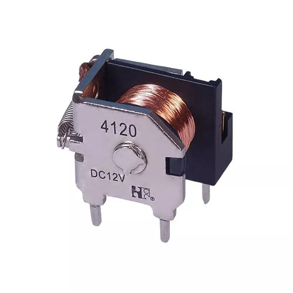
In our factory, we manufacture Automotive Relay units that are specifically designed for this interface role. Our relays are tested for coil-to-contact isolation at 500 VAC and for contact-to-contact isolation at 500 VAC. This ensures that a fault in one circuit cannot propagate to another.
2. What Role Do Relays Play in Managing Inrush Current and Inductive Loads?
Many vehicle loads are inductive, meaning they contain coils that store energy in a magnetic field. When the relay contacts open, the collapsing magnetic field generates a high voltage spike that can arc across the contacts. This is particularly true for motors, solenoids, and transformers. The Automotive Relay must be designed to withstand these spikes without welding its contacts or degrading its performance. The table below shows the typical inrush current and inductive energy for common vehicle loads.
| Load type | Steady-state current (A) | Inrush current (A) | Inductive energy (mJ) | Relay contact requirement |
| Cooling fan motor | 15 – 25 | 60 – 100 | 50 – 120 | High inrush capability |
| Headlight (halogen) | 4 – 6 | 20 – 30 | 5 – 15 | Standard silver contacts |
| Starter solenoid | 30 – 50 | 150 – 250 | 200 – 400 | Silver tin oxide contacts |
| Power window motor | 5 – 10 | 25 – 40 | 20 – 50 | Silver nickel contacts |
| ABS pump motor | 20 – 40 | 80 – 150 | 100 – 200 | High reliability contacts |
Ningbo Forward Relay Corp., Ltd. manufactures Automotive Relay units with contact materials that are specifically selected for each load type. For high inrush loads, we use silver tin oxide contacts that resist welding. For inductive loads, we use silver nickel contacts that handle the energy without excessive erosion. We also offer relays with built-in arc suppression diodes or varistors for the most demanding applications.
3. What Are the Key Electrical and Mechanical Parameters for Relay Selection?
Selecting the right Automotive Relay for a vehicle application requires matching five key parameters to the load and environmental conditions. The table below shows these parameters and their typical ranges for different vehicle applications.
| Parameter | Typical range | Considerations for vehicle design |
| Coil voltage | 12V or 24V (nominal) | Must match vehicle electrical system |
| Coil resistance | 70 – 200 ohms (12V) | Determines coil current and power consumption |
| Contact current rating | 20A, 30A, 40A, 70A | Must exceed steady-state load current |
| Contact arrangement | SPST, SPDT, DPST, DPDT | Determines control flexibility |
| Operating temperature | -40°C to +125°C | Engine compartment relays require higher rating |
| Mechanical life | 10 million operations | Determines relay replacement interval |
| Electrical life | 100,000 operations at rated load | Determines maintenance schedule |
Our factory tests every Automotive Relay for coil resistance, contact resistance, and dielectric strength. We also perform a 100 percent functional test at the end of the production line to ensure that the relay meets its specifications. The mechanical life of our relays is verified by a cycling test that runs 10 million operations.
4. How Do Relays Improve System Reliability Compared to Semiconductor Switches?
Semiconductor switches, such as MOSFETs, have become more common in vehicle electrical systems. They offer silent operation, no moving parts, and fast switching. However, they also have limitations that make electromechanical relays the preferred choice in many applications. The first is voltage drop. A MOSFET has a voltage drop of 0.1 to 0.5V, which generates heat and wastes power. A relay has a voltage drop of less than 0.1V, which is negligible. The second is leakage current. A MOSFET leaks a small current even when it is off (typically 1 to 10 microamps). This can drain a battery over time if the vehicle is not driven regularly. A relay provides true galvanic isolation with zero leakage current. The third is cost. A relay that can switch 40A costs $1 to $3. An equivalent MOSFET would cost $5 to $15. The fourth is robustness. A relay can withstand voltage spikes and short circuits that would destroy a MOSFET. This is why relays are still used in the starter circuit, the cooling fan circuit, and the ABS pump circuit.
Frequently Asked Questions About Automotive Relays in Vehicle Electrical Systems
Summary for Vehicle Electrical Engineers
Automotive Relay units are essential components in modern vehicle electrical systems. They provide the interface between low-power control electronics and high-power loads, protect sensitive circuits from voltage spikes, and offer a level of robustness and cost-effectiveness that semiconductor switches cannot match. The selection of the correct relay for each application depends on the load type, the inrush current, the environmental conditions, and the required reliability. Our factory has been manufacturing Automotive Relay units for over 18 years and supplies to vehicle manufacturers and Tier 1 suppliers worldwide.
Ningbo Forward Relay Corp., Ltd. manufactures a full range of Automotive Relay units, including sealed relays for engine compartments, high-current relays for starter circuits, and micro relays for body control applications. We provide full technical documentation and test reports for each product.