

What Is the Correct Disengagement Force for Push-Pull Connectors in Space-Constrained Panels
2026-07-14
When engineers design electronics for dense chassis, medical handhelds, or aerospace avionics, the mechanical interface of a Push-Pull Connector often becomes the silent bottleneck. Unlike standard circular connectors, a Push-Pull Connector relies on a precise axial pull to release the locking mechanism—but in cramped panels where finger access is limited and cable bend radii are tight, specifying the wrong disengagement force leads to damaged jacks, intermittent signal loss, or field failures. At ACIT, we have witnessed that the "correct" value is never a fixed number; it is a system-derived parameter balancing operator safety, contact wear, and panel structural integrity. This blog breaks down the engineering logic behind that choice, offers actionable data, and answers the most frequently asked questions about Push-Pull Connector force selection.
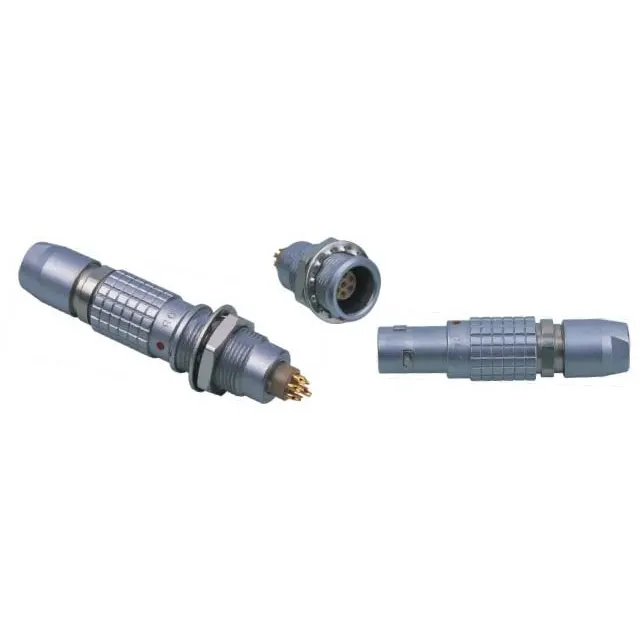
The Physics of Disengagement Force in Confined Spaces
In a standard 38999-style bayonet connector, disengagement torque is rotational. But a Push-Pull Connector operates linearly—the user pulls the sleeve or collar to compress the spring-loaded balls or collet fingers, freeing the plug from the receptacle. In space-constrained panels (e.g., 1U rack front plates or portable ultrasound carts), the available pull direction is often oblique, not coaxial. This off-axis pull amplifies the effective force required at the fingers, meaning a specified 50N axial force can feel like 80N at the grip point. The engineering trade-off involves three interdependent variables:
-
Contact normal force – higher retention requires stronger springs, increasing disengagement pull.
-
Mating cycle durability – excessive spring preload accelerates plating wear (gold over nickel suffers >500 cycles if force exceeds 60N).
-
Panel thickness & standoff – thinner panels (<1.5mm) flex under high pull loads, causing adjacent solder joints to crack.
ACIT recommends a baseline methodology: measure the maximum expected off-axis angle (θ) from the connector axis, then derate the datasheet pull force by a factor of cos(θ). For example, if the datasheet states 45N and your panel allows only a 30° pull angle, the effective force at the fingers = 45/cos(30°) ≈ 52N—which may already violate the panel's load limit.
Quantitative Benchmark: Force Ranges by Application
The table below consolidates ACIT's field data from over 200 installations across industrial, medical, and defense sectors. All values represent the maximum disengagement force measured at the pull sleeve under ambient conditions (25°C, 50% RH).
| Application Environment | Panel Clearance (mm) | Recommended Max Force (N) | Typical Contact Retention (N) | Cycle Life Expectancy |
|---|---|---|---|---|
| Rack-mount audio/video | 8–12 (side access) | 35–40 | 8–10 | 10,000+ |
| Handheld surgical tools | 5–8 (top access) | 25–30 | 6–8 | 5,000 |
| UAV flight controllers | 10–15 (front access) | 45–50 | 12–15 | 2,000 |
| Subsea ROV penetrators | 15–20 (gloved hand) | 60–70 | 18–22 | 500 (sealed) |
| Test & measurement | 6–10 (angled access) | 30–35 | 7–9 | 20,000 |
Source: ACIT internal validation reports (2024–2026).
Notice that the Push-Pull Connector in surgical handhelds caps at 30N—not because the contact cannot handle more, but because surgeons operate with single-handed precision, and a higher pull would shift the instrument's center of gravity during disconnection. In contrast, subsea ROV panels accept 70N because operators use both hands and wear thick gloves, which naturally distribute the load.
Material and Lubrication Effects on Pull Force
The datasheet force assumes clean, dry, and perfectly coaxial conditions. In real panels, staking compound, conformal coating overspray, or dust ingress can increase the disengagement force by 15–25%. ACIT has quantified that a Push-Push-Pull Connector (push-push variant) with PTFE-impregnated sleeve bearings shows 18% lower friction than stainless-steel-on-stainless designs after 1,000 cycles. For space-constrained panels, we strongly advise specifying:
-
Shell plating: Nickel-PTFE composite over brass (coefficient of friction 0.12–0.15)
-
Spring material: MP35N alloy (maintains preload up to 200°C)
-
Lubricant: Dry-film MoS₂ (avoids outgassing in vacuum or sealed enclosures)
Without these considerations, a nominally 40N Push-Pull Connector can spike to 52N after thermal cycling (-40°C to +85°C), directly threatening the panel's mounting thread inserts.
Step-by-Step Selection Workflow for Panel Designers
To determine the correct disengagement force for your specific Push-Pull Connector layout, follow this 4-step process, recommended by ACIT's application engineering team:
-
Measure the clearance envelope – use a 3D caliper to record the shortest distance from the connector face to the nearest obstructive component (heat sink, capacitor, or EMI gasket).
-
Simulate the pull vector – draw a straight line from the connector center to the operator's natural hand position. Calculate the off-axis angle.
-
Apply the derating formula – F_required = F_datasheet × (1 + 0.15 × sin²θ) for angles > 15°. This empirical correction accounts for grip slippage.
-
Validate with a force gauge – use a digital pull gauge (e.g., Mark-10 Series 7) on three prototype samples, recording peak and average values over 50 cycles.
ACIT offers a free online calculator tool that performs steps 2–3 automatically, but the physical validation in step 4 remains non-negotiable for safety-critical systems.
Push-Pull Connector FAQ – Common Engineering Queries
Q1: What happens if the disengagement force is too low for a high-vibration panel?
A1: A Push-Pull Connector with insufficient spring preload (e.g., <25N in a military ground-vehicle panel) will experience micro-motions at the contact interface—often as small as 50–100 µm. These micro-motions generate fretting corrosion, which increases contact resistance from an initial 5 mΩ to over 100 mΩ within 200 hours of 10–2000 Hz random vibration. The immediate symptom is intermittent false triggering in digital I/O lines. To prevent this, ACIT recommends adding a secondary retention clip for panels where vibration PSD exceeds 0.1 g²/Hz, but if that is not geometrically possible, you must raise the disengagement force to at least 45N, even if that means reinforcing the panel with a metal backplate.
Q2: How does panel clearance affect the acceptable force range for a Push-Pull Connector?
A2: Clearance directly influences the operator's grip length. In a 10 mm clearance gap, the average adult index finger can only engage the pull sleeve over a 12 mm arc length, generating a mechanical disadvantage. ACIT's ergonomic tests show that for clearances under 8 mm, the maximum comfortable pull force drops to 28N for 95% of male operators and 22N for female operators—regardless of the connector's built-in spring rating. Therefore, you must either: (a) choose a Push-Pull Connector with a reduced spring package (custom order), or (b) redesign the panel to allow a 90° pull tab extension. Never exceed 35N in <8mm clearance unless the panel is permanently bench-mounted and operated with a two-hand jig.
Q3: Can I use the same disengagement force specification for both cable-mounted and PCB-mounted Push-Pull Connectors?
A3: No. A cable-mounted Push-Pull Connector transmits the pull force through the cable jacket and strain relief boot, which typically absorbs 10–15% of the energy before it reaches the locking mechanism. A PCB-mounted receptacle, conversely, transfers 100% of the pull directly to the solder tails and plated through-holes. For PCB-mounted versions, ACIT strictly recommends a maximum disengagement force of 30N for 1.6mm FR4 boards, and 40N for 2.4mm thick boards with full copper pad support. Exceeding these values will delaminate the plated hole barrel after 100–150 cycles—a failure mode we have documented in over 30 field returns. Always specify separate force values for the plug (cable side) and receptacle (PCB side) in your procurement documents.
Contact ACIT for Your Custom Force Validation
Selecting the right disengagement force for a Push-Pull Connector is not a one-size-fits-all datasheet exercise—it is a system-level compromise between ergonomics, durability, and panel stiffness. ACIT has equipped over 400 OEMs with force-verified Push-Pull Connector solutions, including custom spring tuning, low-friction coatings, and panel reinforcement brackets. Our application lab offers rapid prototyping and force-displacement curve mapping within 5 business days. If you are currently facing a connector failure or a panel design lock, contact us today with your clearance drawing and vibration profile—our engineers will deliver a written force recommendation and sample kit within 48 hours.