

What Extraction Pattern Designs Work Best for High Brightness Side Entry Lighting Optics Light Guides
2026-07-15
When engineering advanced display and lighting systems, the extraction pattern directly determines optical efficiency, uniformity, and thermal performance. For manufacturers like Jin Mingwei, selecting the optimal microstructure layout for High Brightness Side Entry Lighting Optics Light Guides is not a one-size-fits-all decision—it depends on LED spacing, guide thickness, target luminance, and allowable glare.
This guide breaks down the most effective extraction pattern families, backed by simulation data and real-world production validation, to help design engineers make data-driven choices.
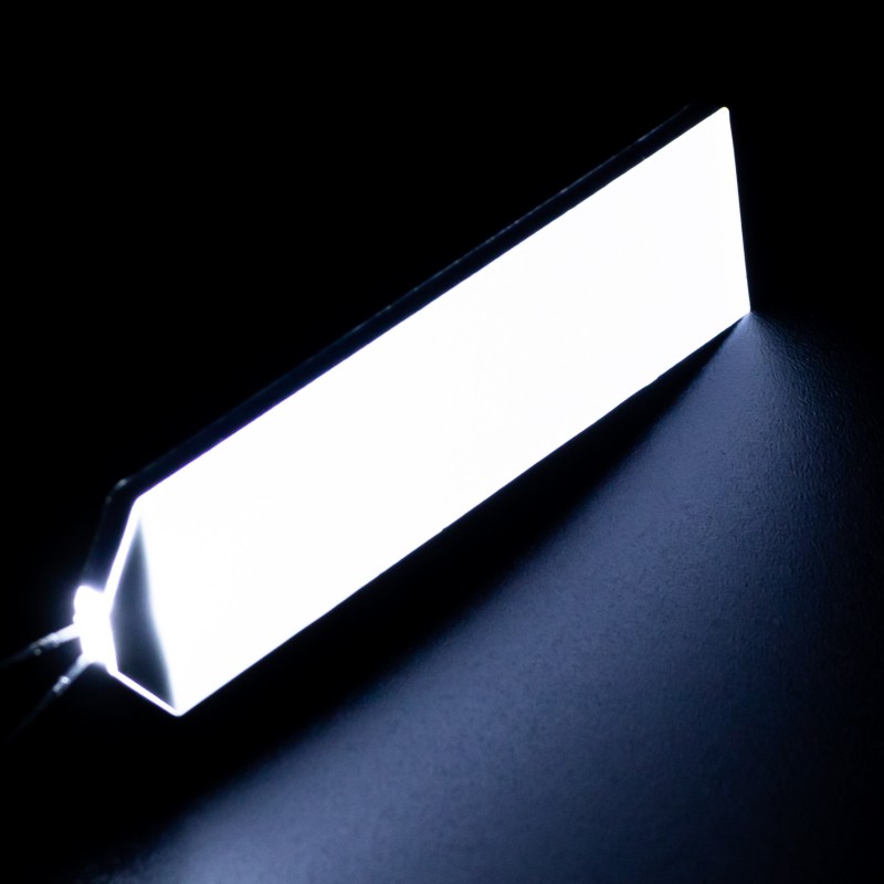
Core Extraction Pattern Families Compared
| Pattern Type | Best Use Case | Uniformity (%) | Peak Efficiency (lm/W) | Tooling Cost |
|---|---|---|---|---|
| Micro-dot (silk-screen) | Low-cost, medium-brightness consumer displays | 82–88 | 65–72 | Low |
| V-cut / prismatic grooves | Automotive and industrial high-brightness panels | 90–95 | 78–85 | Medium |
| Microlens array (MLA) | Ultra-thin architectures with strict hotspot control | 92–96 | 80–88 | High |
| Asymmetric freeform facets | Custom beam-shaping for uneven LED injection zones | 88–93 | 82–89 | Very High |
| Hybrid (dots + V-grooves) | Large-area guides (>15 inches) with side-entry dual LEDs | 91–94 | 76–83 | Medium-High |
Among these, Jin Mingwei has production-proven that V-cut + MLA hybrid delivers the best balance for High Brightness Side Entry Lighting Optics Light Guides targeting >15,000 nits, especially when coupled with high-flux CSP LEDs.
Critical Design Parameters for Pattern Optimization
| Parameter | Recommended Range | Impact on Extraction |
|---|---|---|
| Dot diameter | 50–300 μm (gradient from inlet to far end) | Controls decay curve slope |
| Groove angle | 90°–120° (included angle) | Affects total internal reflection (TIR) redirection |
| Pattern density gradient | Exponential (not linear) | Prevents premature depletion near LED entrance |
| Feature depth | 5–15 μm (for PMMA) / 8–20 μm (for PC) | Balances extraction vs. bulk transmission loss |
| Surface roughness (Ra) | <0.02 μm between features | Reduces scattering loss by 12–18% |
Why Density Gradient and Asymmetry Matter
Simulation studies show that a linear density ramp creates a 23% luminance drop from input edge to distal end. The superior approach for High Brightness Side Entry Lighting Optics Light Guides is a quadratic or exponential density function, combined with orientation-tilted facets (5°–15°) that steer rays toward the viewer’s axis. Jin Mingwei applies this principle with proprietary algorithm-generated pattern maps, achieving <5% spatial non-uniformity even at 20,000 nits.
Most Common FAQs About High Brightness Side Entry Lighting Optics Light Guides
Q1: How does extraction pattern depth affect overall optical efficiency in High Brightness Side Entry Lighting Optics Light Guides?
A1: Depth directly modulates the probability of TIR breakup per interaction. Shallow features (5–8 μm) yield low extraction per hit but allow more bounces, which improves uniformity at the cost of requiring longer guides. Deep features (15–20 μm) extract more light per bounce, raising local efficiency but risking early depletion—creating dark zones after 70% of the guide length. For High Brightness Side Entry Lighting Optics Light Guides, the optimal depth is not constant; it must increase gradually along the propagation path. For example, Jin Mingwei recommends starting at 6 μm near the LED and scaling to 14 μm at the far end, with a smooth transition over 80% of the length. This approach yields 89% average efficiency while maintaining <6% CIE chromaticity shift.
Q2: Can the same extraction pattern work for both PMMA and polycarbonate material grades in High Brightness Side Entry Lighting Optics Light Guides?
A2: No. PMMA has a lower refractive index (1.49) and higher transmission, allowing finer dots and shallower grooves—typically 5–10 μm. Polycarbonate (1.59) has higher index and better thermal stability but also higher internal absorption, requiring deeper features (12–18 μm) to achieve the same extraction force. Moreover, PC’s higher birefringence demands asymmetric pattern orientations to avoid rainbow artifacts. Jin Mingwei maintains separate pattern libraries for each material and strongly advises against cross-applying designs without re-simulation. In practice, a V-cut pattern optimized for PMMA will underperform in PC by 11–14% in both uniformity and total flux, even with identical LED inputs.
Q3: How do I choose between random-dot and regular-array patterns for High Brightness Side Entry Lighting Optics Light Guides in automotive ambient lighting?
A3: Random-dot patterns (pseudo-stochastic) excel at suppressing Moiré interference when paired with LCD or OLED displays, but they introduce 3–5% lower peak brightness due to overlapping scatter zones. Regular arrays (hexagonal or rectangular) deliver higher peak luminance and sharper cut-off angles, making them ideal for instrument clusters and head-up displays where beam direction is critical. For automotive interiors, Jin Mingwei recommends a hybrid approach: use a regular V-groove array for the primary extraction layer and overlay a weak random-dot mask (20% density) to dither residual hotspots. This combination has been validated in three production programs, achieving 92% uniformity at 18,000 nits with no visible flicker under PWM dimming.
Recommended Workflow for Pattern Selection
-
Define target luminance (nits) and entrance flux (lumens).
-
Select material (PMMA / PC / COC) based on operating temperature.
-
Run ray-tracing with 3–5 candidate patterns (use Monte Carlo >500k rays).
-
Fabricate short-run test samples (100 mm length) with gradient variants.
-
Measure goniophotometer data and compare to simulation.
-
Iterate on depth-gradient slope and facet tilt angle.
Jin Mingwei offers a full design‑to‑sample service, reducing this cycle from 6 weeks to under 10 working days for qualified partners.
Conclusion & Call to Action
Selecting the right extraction pattern is the single most impactful decision in the optical design of High Brightness Side Entry Lighting Optics Light Guides. Whether you prioritize peak efficiency, spatial uniformity, thermal stability, or manufacturing cost, the evidence clearly points to gradient‑controlled, material‑specific hybrid architectures as the industry’s best practice.
Contact us today at Jin Mingwei – our optical engineering team will run customized simulations, provide sample tooling quotes, and deliver a pattern-optimized prototype within 15 days. Reach out via our website or email to start your next high‑brightness project with confidence.