

What Challenges Do Engineers Face When Designing Riglex Circuits
2026-03-03
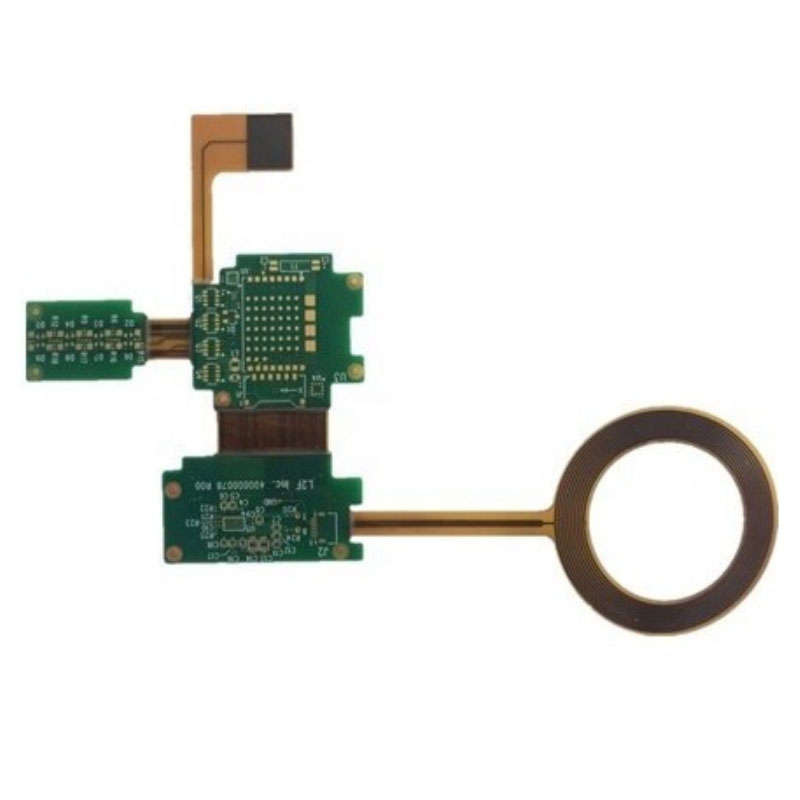
The demand for smaller, lighter, and more complex electronic devices has propelled Rigid-Flex Boards to the forefront of modern PCB engineering. These hybrids combine the best of both worlds: the stability of rigid layers for component mounting and the flexibility of polyimide films for dynamic bending. However, transitioning to this advanced technology is not without its hurdles. At Akeson, we understand that navigating the complexities of Rigid-Flex Boards requires specialized knowledge to avoid costly prototyping errors and manufacturing delays.
Below, we break down the primary engineering obstacles and how to mitigate them.
Critical Design Challenges and Solutions
To ensure the reliability and functionality of your project, engineers must address specific mechanical and electrical constraints. Here are the most common challenges encountered during the design phase.
| Challenge | Description | Mitigation Strategy |
|---|---|---|
| Bend Radius Violations | Bending the flexible layer too sharply can cause micro-fractures in the copper traces, leading to open circuits. | Maintain a bend radius of at least 10:1 (thickness:radius) for dynamic flexing. Use Akeson’s design guidelines for tapered traces. |
| Layer Stack-Up Complexity | Incorrect layer transitions between rigid and flex sections can create mechanical stress points. | Utilize a "step-down" or "tapered" stack-up design. Ensure the transition zone is supported to prevent adhesive squeeze-out. |
| Copper Fatigue | Repeated flexing cycles can work-harden and break standard copper. | Specify rolled annealed copper instead of electro-deposited copper for dynamic flex areas. |
| Impedance Control | Maintaining consistent impedance across the transition from rigid to flex material is difficult due to varying dielectric constants. | Perform 3D field solving simulations. Maintain consistent trace geometry and reference plane integrity across the entire path. |
Key Engineering Considerations
Beyond the table above, engineers must also contend with material selection and component placement. The wrong choice here can render a highly flexible board useless.
-
Component Placement: Avoid placing heavy components or vias on the flex region. These areas must remain free for bending. Always place stiffeners under connectors if required.
-
Adhesive vs. Adhesiveless: For high-reliability applications, adhesiveless laminates are preferred as they offer better thermal stability and thinner profiles, a specialty of manufacturers like Akeson.
Rigid-Flex Boards FAQ
To further clarify the complexities of these designs, here are answers to three of the most frequently asked questions regarding Rigid-Flex Boards.
What is the most common cause of failure in Rigid-Flex Boards?
The most common cause of failure is stress concentration at the interface where the rigid and flexible sections meet. If the transition is not properly supported or if the bend radius is too tight, the repeated mechanical stress will eventually cause the copper traces to crack. This is why proper strain relief and gradual tapering of materials in the transition zone are critical in high-quality Rigid-Flex Boards.
How do I choose the right coverlay versus solder mask on the flex section?
For the flexible portion of the circuit, standard solder mask is generally too brittle and will crack when bent. Engineers must specify a flexible coverlay (typically polyimide film with adhesive). This coverlay protects the circuits while maintaining flexibility. Solder mask is generally reserved for the rigid sections of the board where components are soldered.
Can Rigid-Flex Boards be repaired if a trace breaks?
Repairing Rigid-Flex Boards is extremely difficult and often not recommended. Because the flexible substrate is delicate and the circuits are often buried between layers of polyimide, attempting to solder a jumper wire can easily melt the surrounding materials or create new stress points. In most cases, if a flex circuit fails, the entire assembly must be replaced. This underscores the importance of getting the design right the first time with a reliable fabrication partner.
Conclusion
Designing Rigid-Flex Boards requires a delicate balance between mechanical engineering and electrical performance. By understanding the pitfalls of bend radius, material fatigue, and stack-up design, you can ensure a robust and long-lasting product.
Are you ready to bring your complex design to life? Ensure your project's success with expert manufacturing.
Contact Us at Akeson today for a design for manufacturability review and a free quote on your next Rigid-Flex project.