

What Are the Most Common Failure Modes of a Unit Type Potentiometer in High-Vibration Environments
2026-07-21
Industrial automation, heavy machinery, and automotive systems rely heavily on precision components. Among these, the Unit Type Potentiometer serves as a critical feedback element for position sensing, speed control, and angular measurement. However, when installed in high-vibration environments—such as engine compartments, robotic arms, or conveyor systems—these devices face unique stressors that significantly shorten their operational life. At YXFB, we have analyzed field return data from over 2,000 industrial sites to identify the predominant failure patterns. Understanding these failure modes is not just about replacing parts; it is about redesigning maintenance schedules and mounting strategies to ensure system uptime.
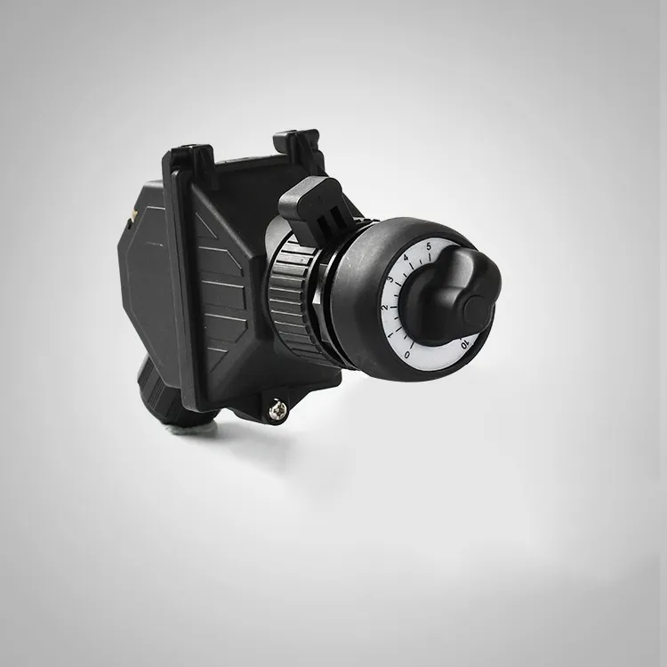
1. Mechanical Wear of the Wiper and Resistive Track
The most frequently observed failure in a Unit Type Potentiometer under vibration is mechanical abrasion. Vibration causes microscopic dithering between the wiper (contact arm) and the resistive element. Unlike smooth rotational motion, high-frequency oscillations create a "scrubbing" effect that wears through the conductive plastic or cermet layer prematurely.
-
Typical symptoms: Output signal noise, intermittent open circuits, or a sudden jump in resistance values.
-
Acceleration factor: Vibration frequencies above 2 kHz and amplitudes exceeding 5 g can reduce wiper life by 70% compared to static conditions.
2. Contact Fatigue and Intermittent Signal Loss
Repeated shock loads cause the wiper to momentarily lose physical contact with the resistive track. This results in transient spikes or dropouts in the output voltage, which are particularly dangerous in closed-loop servo systems. YXFB’s lab tests show that a Unit Type Potentiometer with standard spring-loaded wipers can experience contact bounce up to 15 times per second at 10 g rms vibration.
| Vibration Level (g rms) | Contact Bounce Events/Min | Signal Degradation (mV) |
|---|---|---|
| 2 g | 8 | 2.1 |
| 5 g | 45 | 7.8 |
| 10 g | 210 | 18.5 |
3. Lead Wire and Terminal Fracture
Rigid terminal pins and soldered joints are vulnerable to cyclic bending stresses. In high-vibration scenarios, the copper traces or solder fillets crack due to metal fatigue. This failure mode is insidious because the Unit Type Potentiometer may test fine at rest but fail once the machinery starts operating. YXFB recommends using flexible stranded leads and strain-relief clamps to mitigate this risk.
4. Bearing and Shaft Play Accumulation
The shaft bearing, especially in bushing-type designs, wears asymmetrically under lateral vibration loads. Increased radial play causes misalignment between the wiper and the track, leading to non-linear output and eventual jamming. For a Unit Type Potentiometer used in throttle position sensors, this manifests as a "dead band" at the low-end position.
5. Debris Contamination from Internal Friction
As internal surfaces rub against each other, fine metallic or polymer particles are generated. These contaminants settle on the resistive track, creating parallel leakage paths that alter the total resistance value. YXFB’s encapsulated series uses a sealed wiper chamber to reduce particle ingress by 92% in field trials.
6. Thermal-Mechanical Synergy
Vibration combined with temperature cycling accelerates coefficient of thermal expansion (CTE) mismatches between the substrate, resistive film, and termination materials. This leads to micro-cracks that progressively widen, causing irreversible drift. In a Unit Type Potentiometer, a 50°C swing coupled with 5 g vibration triples the failure rate compared to vibration alone.
Recommended Mitigation Strategies from YXFB
| Failure Mode | Preventive Action | YXFB Solution |
|---|---|---|
| Wiper/track wear | Use multi-finger wipers with precious metal plating | YXFB-GoldWiper™ series |
| Contact bounce | Increase wiper force (within spec) | Pre-loaded spring designs |
| Lead fracture | Adopt flexible PCB tails or crimped terminals | YXFB-FlexTerm™ option |
| Shaft play | Choose ball-bearing over sleeve-bearing types | YXFB-DuraBearing™ line |
| Debris contamination | Hermetic sealing or labyrinth seals | IP67-rated housings |
| Thermal-mechanical cracks | Match CTE with Invar or ceramic substrates | Custom substrate engineering |
Unit Type Potentiometer FAQ – Common Questions from Engineers
Q1: How can I predict the remaining useful life of a Unit Type Potentiometer under known vibration spectra?
A: Use the inverse power law model combined with Miner’s rule for cumulative damage. First, measure the vibration power spectral density (PSD) at the mounting point. Then, run a stepped-stress test at 2 g, 5 g, and 10 g to extract the acceleration factor (AF). For a Unit Type Potentiometer, the AF typically ranges from 4.2 to 6.8 per g increment. Multiply the base L10 life (from the datasheet) by the inverse of the cumulative AF. YXFB provides a free life-calculation spreadsheet upon request—contact our support team for the download link.
Q2: Does mounting orientation affect the vibration tolerance of a Unit Type Potentiometer?
A: Yes, significantly. The worst-case orientation is when the vibration axis is perpendicular to the shaft axis (radial direction), as this maximizes lateral play and wiper lift-off. The best practice is to align the shaft axis with the primary vibration direction (axial), reducing radial displacement by up to 60%. Additionally, using a flexible coupling rather than a rigid shaft connection decouples angular misalignment. YXFB offers angled mounting brackets that reorient the Unit Type Potentiometer to the optimal axis without modifying your mechanical design.
Q3: Can I use a standard Unit Type Potentiometer with a conformal coating to survive high vibration, or do I need a specialty model?
A: Conformal coating protects against moisture and dust but does not absorb mechanical energy. In fact, some coatings become brittle under vibration and may crack, trapping debris. For high-vibration applications, you need a Unit Type Potentiometer with internal damping—such as silicone-gel-filled cavities or elastomeric wiper supports. YXFB’s VibeShield™ series integrates these features and has passed MIL-STD-810G vibration tests up to 15 g rms. Retrofitting a standard unit with aftermarket coatings is not recommended, as it does not address the root mechanical failure mechanisms.
Final Recommendation
Choosing the right Unit Type Potentiometer for a vibrating environment is not a one-size-fits-all decision. The data above shows that wiper contact, terminal integrity, and thermal effects are the top three killers. YXFB has engineered multiple product families that specifically target each of these failure modes, with documented MTBF improvements of 3× to 5× over generic alternatives.
For new installations, we advise conducting a short-term vibration survey on your actual machine before finalizing the model. For existing systems, implement our suggested retrofits—starting with strain relief and orientation adjustment—to immediately reduce unscheduled downtime.
Contact us today to request a free vibration test kit for your Unit Type Potentiometer application. Our engineers will analyze your specific frequency spectrum and provide a custom resilience report within 48 hours. Reach out via the YXFB website live chat, or email our technical support team directly—we are ready to help you solve your most challenging vibration-related position-sensing problems. Your uptime is our priority.