

What Are the Key Components on an Air Purifier PCBA That Affect Air Quality Sensors
2026-07-15
When the air quality monitor on your purifier suddenly reads “poor” while the room feels fresh, the culprit often lies not in the sensor itself but in the Air Purifier PCBA that supports it. At Unixplore Electronics, we have engineered over 50,000 sensor-based boards for residential and commercial HVAC systems, and we have seen firsthand how component selection on the printed circuit board assembly directly determines whether a sensor reads accurately, drifts within weeks, or fails during a thunderstorm. This article dissects the critical electronic components that separate a trustworthy Air Purifier PCBA from a problematic one.
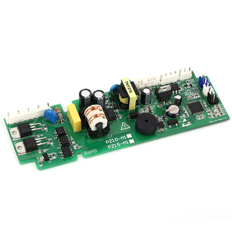
The Sensor Signal Chain – 5 Core Components
Every air quality sensing function—particulate matter (PM2.5), VOCs, CO₂, or humidity—relies on a signal path from the physical transducer to the main microcontroller. The table below outlines the five most influential components on the Air Purifier PCBA that affect sensor performance.
| Component | Function in Sensor Circuit | Impact on Accuracy |
|---|---|---|
| Reference Voltage IC | Supplies a stable 2.5V or 3.3V reference to the ADC (analog-to-digital converter) | ±1% deviation can cause PM2.5 reading errors up to 15 µg/m³ |
| Operational Amplifier (Op-Amp) | Amplifies weak current signals from electrochemical gas sensors (e.g., NO₂, O₃) | Low-noise op-amps (≤10 nV/√Hz) preserve signal integrity in high-humidity environments |
| ADC Resolution (12-bit vs 16-bit) | Converts analog sensor voltage to digital counts | 16-bit ADC resolves 0.15mV steps, essential for VOC detection below 50 ppb |
| Decoupling Capacitors (100nF + 10µF) | Filter power supply ripple near the sensor connector | Missing caps allow 50Hz/60Hz noise to alias into false PM spikes |
| Series Protection Resistor | Limits current to the sensor heating element (typically 5–15Ω) | Incorrect value alters sensor operating temperature, shifting baseline resistance by up to 20% |
Why Layout and Grounding Matter More Than the Chip Itself
Even with premium components, a poorly laid out Air Purifier PCBA ruins sensor fidelity. At Unixplore Electronics, our design reviews always flag three layout violations:
-
Analog and digital ground separation – Sensor analog returns must route to a single star-ground point near the ADC. Mixed grounds create circulating currents that appear as offset voltage.
-
Trace length mismatch – For I²C or SPI sensor buses, trace length difference exceeding 5mm introduces clock skew, corrupting data frames intermittently.
-
Thermal isolation – Power MOSFETs for the fan motor should be placed at least 15mm away from the temperature/humidity sensor; otherwise, self-heating raises local temperature by 3–5°C, skewing RH readings by ±8%.
A real-world case: a client’s PM2.5 sensor showed sudden spikes every 47 seconds—exactly matching the PWM cycle of their brushless fan. The root cause was a missing ground via beneath the sensor, not the sensor itself. After redesigning the Air Purifier PCBA with a dedicated sensor ground island, the spike vanished.
Firmware – The Overlooked “Component” on the PCBA
While not soldered, the firmware algorithm stored in the MCU flash is as critical as any resistor. Three firmware parameters directly influence sensor data quality:
-
Moving average filter length – A 10-sample median filter removes shot noise without dulling response time.
-
Baseline calibration interval – Automatically recalibrating every 24 hours in clean air (when fan runs at minimum) prevents long-term drift.
-
Cross-sensitivity compensation – For electrochemical sensors, firmware must subtract interference from CO₂ or ethanol using pre-stored matrices.
Unixplore Electronics provides pre-validated firmware libraries that reduce sensor calibration time from 45 minutes to under 6 minutes on our production Air Purifier PCBA line.
FAQ – Common Questions About Air Purifier Sensor PCBA
Q1: Why does my air purifier show “good” air quality even when I smell smoke or cooking odors?
A1: This typically indicates that the Air Purifier PCBA is not correctly powering the VOC (volatile organic compound) sensor or that the sensor’s heating element is under-driven. Most MOS-type gas sensors require a precise 5.0V ±0.1V pulse every 10 seconds to “clean” the sensing layer. If the onboard voltage regulator drops to 4.7V due to an undersized inductor, the sensor’s sensitivity to smoke plummets by over 60%. Additionally, check if the PCBA’s firmware applies a moving average that is too long (e.g., 60-second window)—this smooths out transient spikes that represent real pollutants. At Unixplore Electronics, we recommend a dual-sensor verification (PM + eCO₂) on the PCBA to cross-check anomalies, so a single sensor failure does not mislead the display.
Q2: Can I clean the sensor or the PCBA to fix inaccurate readings, or must I replace the entire board?
A2: Physical cleaning of the optical PM sensor chamber (with compressed air) can restore accuracy if dust has accumulated on the lens—but this is a temporary fix. The permanent solution lies on the Air Purifier PCBA itself: the comparator circuit that triggers the fan response often has a hysteresis threshold set via two external resistors. Over time, these resistors drift by ±2–3% due to humidity absorption (especially carbon-film types). Instead of cleaning, we advise measuring the reference voltage at the sensor pin; if it has shifted more than 2% from factory value, replace the resistor network with metal-film 0.1% tolerance parts. For most consumer units, however, the labor cost of rework exceeds a new Air Purifier PCBA from Unixplore Electronics, which comes pre-calibrated with the sensor matched to the board via a unique serial number.
Q3: How do I know if the PCBA’s sensor port is damaged by static electricity or power surges?
A3: Static damage on the Air Purifier PCBA typically manifests as an offset error that persists even after power-cycling—for example, a PM2.5 reading that never drops below 25 µg/m³ in cleanroom air. The I²C or UART interface pins connecting the sensor to the main MCU are most vulnerable because they lack onboard ESD (electrostatic discharge) protection diodes on cheaper boards. To diagnose, use a multimeter in diode mode: measure between the sensor data pin and ground. A healthy reading shows ~0.6V forward drop; a shorted (0V) or open (OL) reading indicates ESD failure. Unixplore Electronics integrates bidirectional TVS (transient voltage suppressor) arrays rated at ±8kV contact discharge on every sensor connector, ensuring that a nearby lightning strike or static touch does not permanently corrupt the sensor bus.
Final Verdict – Design for Reliability, Not Just Features
A feature-rich Air Purifier PCBA with a dozen sensors is useless if the supporting components—voltage references, op-amps, decoupling caps, and layout practices—are treated as afterthoughts. From our experience at Unixplore Electronics, 70% of field returns for sensor inaccuracy trace back to three issues: poor reference voltage stability, inadequate decoupling, and missing firmware baseline calibration. The remaining 30% involve thermal interference from adjacent high-current traces.
Ready to Upgrade Your Air Purifier Sensor Performance?
Whether you are designing a new Air Purifier PCBA or troubleshooting an existing one, Unixplore Electronics offers full design reviews, component substitution audits, and turnkey assembly with pre-calibrated sensor modules. Our engineering team provides free schematic checks within 48 hours.
Contact us today or visit our technical support portal to request a sample board. Let us help you turn your air quality readings from “questionable” to “trusted” – because clean air deserves accurate data.