

The Latest Standards & Specifications for Rigid-Flex Printed Circuit Boards
2025-12-26
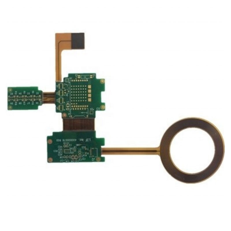
In the rapidly advancing world of electronics, Rigid-Flex Boards have become indispensable for innovative, high-reliability applications. Staying compliant with the latest industry standards is not just a formality; it’s a critical requirement for ensuring performance, reliability, and manufacturability. At Akeson, we specialize in navigating this complex landscape, ensuring every rigid-flex PCB we design and fabricate meets the most current and stringent specifications. This blog outlines the key governing documents essential for any successful rigid-flex project.
The design and manufacturing of rigid-flex circuits are primarily governed by the IPC standards, with a few critical additions.
Primary Governing Standards:
-
IPC-2223D: Sectional Design Standard for Flexible/Rigid-Flexible Printed Boards. This is the foundational document for rigid-flex PCB design, covering materials, mechanical considerations, and conductor routing.
-
IPC-6013E: Qualification and Performance Specification for Flexible/Rigid-Flexible Printed Boards. This standard sets the performance and acceptance criteria for fabricated boards.
-
IPC-J-STD-001: Requirements for Soldered Electrical and Electronic Assemblies. This defines the materials, methods, and verification criteria for high-quality soldering on assemblies that include rigid-flex components.
-
IPC-A-600: Acceptability of Printed Boards. It provides visual quality benchmarks for both rigid and flexible areas.
For material selection, which is paramount for flex endurance, the following specifications are crucial:
| Specification | Title | Key Focus for Rigid-Flex |
|---|---|---|
| IPC-4202 | Flexible Base Dielectrics for Flexible Printed Circuitry | Covers adhesive and adhesiveless polyimide films. |
| IPC-4203 | Adhesive Coated Dielectric Films for Flexible Printed Circuitry | Addresses coverlay and bonding layer materials. |
| IPC-4204 | Flexible Metal-Clad Dielectrics for Flexible Printed Circuitry | Governs the flexible copper-clad laminates (FCCL). |
Rigid-Flex Boards FAQ
Q: How many bend cycles can a standard Akeson rigid-flex design endure?
A: The bend cycle life depends heavily on design, materials, and bend radius. A well-designed static (installed) application from Akeson can last the product's lifetime. For dynamic flexing, using adhesiveless laminates and proper stiffening, designs can reliably achieve thousands to hundreds of thousands of cycles.
Q: What are the most common pitfalls in rigid-flex PCB layout?
A: The most common pitfalls include neglecting the bend area rules (keeping conductors perpendicular to the bend, using hatched polygons), improper transition zone design between rigid and flex areas, and insufficient stiffener support for connectors, which can lead to mechanical failure.
Q: Does Akeson handle the entire process from design to assembly?
A: Yes, Akeson provides a complete turnkey solution. Our expertise flows seamlessly from rigid-flex PCB design consultation and DFM analysis to precision fabrication and final component assembly, ensuring optimal integrity and reliability at every stage.
Navigating the intricate web of rigid-flex PCB standards requires a partner with deep expertise and a commitment to quality. Akeson integrates these specifications into every phase of our process, from initial design review to final testing. This disciplined approach guarantees that your innovative product is built on a foundation of proven reliability and performance.
Do you have a challenging project that demands expert guidance on rigid-flex standards and design? Contact us today to discuss how Akeson can ensure your next rigid-flex board is not only compliant but optimized for excellence.