

How to Select the Right Electronic Components for a Paper Shredder PCBA Design
2026-06-03
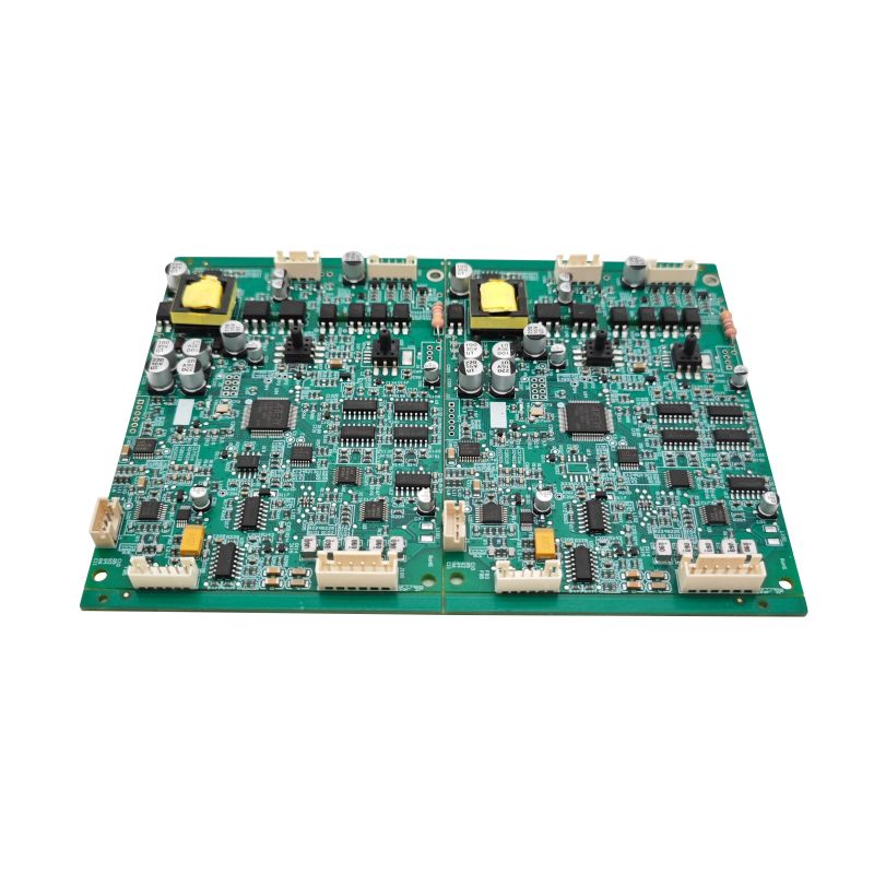
Choosing optimal electronic components for a Paper Shredder PCBA directly determines product reliability, safety, and cost. At Unixplore Electronics, we specialize in industrial-grade PCBA solutions that prevent motor jams, overheating, and electrical failures.
Key Components and Selection Criteria
| Component | Critical Parameters | Recommended Specification |
|---|---|---|
| Motor Driver IC | Current rating, thermal shutdown | ≥15A continuous, 40V max |
| Current Sensing Resistor | Low tolerance, high power | 10mΩ, 3W, ±1% |
| Triac/Relay | Surge current, isolation voltage | 25A surge, 250VAC isolation |
| Optical Sensor | Response time, ambient light immunity | <5µs, built-in Schmitt trigger |
| MCU | I/O pins, ADC resolution | 8-bit, 6 ADC channels |
Four-Step Selection Process
-
Define load profile – Measure stall current of your shredder motor (typically 10–20A for home units, 25–40A for commercial).
-
Overcurrent protection – Use a dedicated Paper Shredder PCBA design with a precision shunt resistor and comparator-based cutoff below 2 seconds.
-
Thermal management – Select MOSFETs with Rds(on) < 10mΩ and add copper pour area ≥ 15cm² on the Paper Shredder PCBA.
-
EMC compliance – Include snubber circuits (100Ω + 0.1µF) across triacs and ferrite beads on sensor lines.
Paper Shredder PCBA FAQ
Q1: How does the current sensing circuit prevent motor burnout on a Paper Shredder PCBA?
A: The Paper Shredder PCBA measures voltage drop across a low-ohm resistor (e.g., 5mΩ to 20mΩ) continuously. When current exceeds a preset threshold (e.g., 15A for 0.5 seconds), the MCU signals the relay driver to cut power. This avoids overheating the motor windings or melting the plastic gearbox. Some designs add a thermal fuse directly on the PCBA for secondary protection.
Q2: Can I use a general-purpose MCU instead of a dedicated motor control chip for a Paper Shredder PCBA?
A: Yes, but you must add external drivers. A general-purpose MCU (like ATmega328P or STM8S) lacks the high-current outputs needed. Your Paper Shredder PCBA will require a separate gate driver (e.g., IR2104) and H-bridge or dual relays. The trade-off is lower unit cost (by $0.80–$1.50) versus higher BOM complexity and risk of EMI noise affecting sensor readings.
Q3: What is the typical lifespan of a well-designed Paper Shredder PCBA under daily office use?
A: With proper component derating (capacitors rated 105°C, MOSFETs at 50% of max drain current), a Paper Shredder PCBA typically lasts 8–10 years or 15,000–20,000 cycles. Most failures occur from swollen electrolytic capacitors (replace with solid polymer types) or relay contact welding (upgrade to 30A-rated relays). Unixplore Electronics designs for 25,000-cycle minimum with accelerated life testing.
Best Practices for High-Reliability Design
-
Separate power and logic grounds on the Paper Shredder PCBA to prevent voltage spikes from corrupting sensor signals.
-
Add varistors (MOVs) across AC inputs – this absorbs line surges up to 6000V.
-
Use conformal coating if the shredder operates in humid environments (e.g., basement offices).
For custom Paper Shredder PCBA design support or component sourcing, contact Unixplore Electronics today for a free design review and BOM optimization quote.