

How Should Thermoelectric Coolers Be Mounted to Maintain Consistent Thermal Contact?
2026-10-23
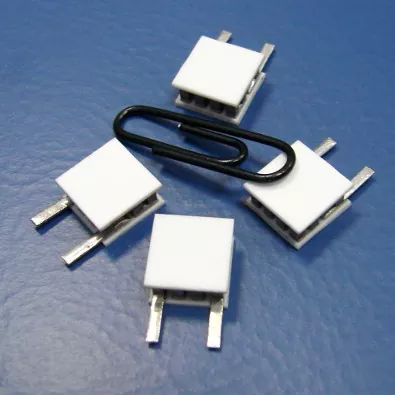
A thermal engineer receives a sample of a portable medical refrigerator for evaluation. The design uses a Thermoelectric Coolers module sandwiched between a cold-side heat sink and a hot-side heat sink. The laboratory test of the module alone shows a temperature differential of 65°C at 12 V. In the assembled unit, the differential is only 40°C, and the cold-side temperature rises after 10 minutes of operation. The engineer measures the contact resistance between the module and the heat sinks. The measured contact resistance is 0.8 K/W, compared to the design target of 0.2 K/W. The high contact resistance is causing the heat to flow back through the module instead of being dissipated by the hot-side heat sink. The cause is improper mounting. This guide explains how to mount thermoelectric coolers to maintain consistent thermal contact.
1. Why Does Contact Pressure Matter for Thermal Contact?
The contact between the Thermoelectric Coolers ceramic surface and the heat sink is not perfect. The surfaces have microscopic peaks and valleys. The actual contact area is only 1 to 5 percent of the apparent area. The heat flows through the contact points and through the air gaps. The air has a thermal conductivity of 0.026 W/mK, which is very low. Increasing the contact pressure deforms the peaks and increases the contact area. The contact resistance decreases as the pressure increases. The table below shows the relationship between contact pressure and contact resistance for a typical thermoelectric cooler.
| Contact pressure (MPa) | Contact resistance (K/W) | Thermal interface material | Recommended application |
| 0.1 | 0.80 | None (dry contact) | Not recommended |
| 0.3 | 0.45 | Thermal grease | Light pressure, low power |
| 0.5 | 0.25 | Thermal grease | Standard application |
| 0.8 | 0.15 | Thermal grease or pad | High power, critical cooling |
| 1.0 | 0.12 | Thermal grease | Maximum recommended |
In our factory, we recommend a contact pressure of 0.5 to 0.8 MPa for our Thermoelectric Coolers. The pressure is achieved by using spring-loaded screws or a clamping bar. The pressure must be uniform across the module. If the pressure is concentrated at one corner, the ceramic can crack. Foshan TEH Electric Appliance Co., Ltd. provides a mounting kit with spring-loaded screws and a pressure distribution plate for each module size.
2. How Does Surface Flatness Affect Contact Resistance?
The flatness of the heat sink surface determines how well it conforms to the Thermoelectric Coolers ceramic. If the heat sink is concave or convex, the contact pressure is concentrated at the center or at the edges, and the contact resistance increases. The recommended flatness for a thermoelectric cooler heat sink is 0.02 mm per 25 mm of length. The surface roughness should be 0.8 to 1.6 microns Ra. The table below shows the effect of surface flatness on contact resistance.
| Surface flatness (mm/25 mm) | Surface roughness (Ra, µm) | Contact resistance (K/W) at 0.5 MPa | Recommendation |
| 0.01 | 0.8 | 0.20 | Excellent |
| 0.02 | 1.6 | 0.25 | Good (standard) |
| 0.05 | 3.2 | 0.40 | Marginal; machine the surface |
| 0.10 | 6.3 | 0.65 | Poor; rework required |
Thermal engineer's note: The heat sink surface must be machined after welding or brazing. The welding process can distort the surface. In our factory, we inspect the flatness of every heat sink before assembly. We use a surface plate and a dial indicator to measure the flatness at five points. If the flatness exceeds 0.05 mm per 25 mm, the heat sink is rejected. We also recommend that the customer verify the flatness of the heat sink before mounting the Thermoelectric Coolers module. A warped heat sink is a common cause of high contact resistance and poor cooling performance.
3. What Thermal Interface Material Should Be Used?
The thermal interface material fills the microscopic gaps between the Thermoelectric Coolers and the heat sink. The material must have a high thermal conductivity, a low thermal resistance, and a thickness that is thin enough to minimize the thermal path but thick enough to fill the gaps. The most common materials are thermal grease, thermal pads, and phase change materials. The table below compares their properties.
| Material | Thermal conductivity (W/mK) | Typical thickness (mm) | Thermal resistance (K/W) | Best application |
| Thermal grease (silicone) | 1.0 – 3.0 | 0.05 – 0.10 | 0.05 – 0.15 | Standard, high pressure |
| Thermal pad (silicone) | 1.5 – 6.0 | 0.5 – 2.0 | 0.20 – 0.50 | Low pressure, easy assembly |
| Phase change material | 1.0 – 2.0 | 0.05 – 0.10 | 0.05 – 0.15 | High reliability, reflow |
| Graphite sheet | 5.0 – 15.0 (in-plane) | 0.1 – 0.3 | 0.10 – 0.25 | High conductivity, electrical isolation |
In our factory, we recommend thermal grease with a thermal conductivity of at least 2.0 W/mK for our Thermoelectric Coolers. The grease should be applied in a thin, uniform layer. A thickness of 0.05 to 0.10 mm is sufficient to fill the gaps without adding excessive thermal resistance. The grease should be applied to both the cold side and the hot side of the module. We also offer a phase change material for applications that require a dry, non-migrating interface. Foshan TEH Electric Appliance Co., Ltd. provides thermal grease and application tools with every module order.
4. How Should the Module Be Secured to Maintain Pressure Over Thermal Cycling?
The mounting system must maintain the contact pressure over thousands of thermal cycles. The module expands and contracts as it heats and cools. If the mounting is rigid, the pressure can increase or decrease, causing the contact resistance to change. The recommended mounting method is to use spring-loaded screws or a Belleville washer stack. The spring maintains a constant force even when the module expands. The table below shows the recommended spring force and deflection for different module sizes.
| Module size (mm) | Recommended spring force (N) | Spring deflection (mm) | Number of screws |
| 20 x 20 | 200 – 300 | 1.0 – 1.5 | 2 |
| 30 x 30 | 400 – 600 | 1.5 – 2.0 | 2 |
| 40 x 40 | 700 – 1,000 | 2.0 – 2.5 | 4 |
| 50 x 50 | 1,100 – 1,500 | 2.5 – 3.0 | 4 |
In our factory, we use spring-loaded screws with a Belleville washer stack for our Thermoelectric Coolers mounting kits. The springs are selected to provide the recommended force at the assembled height. We also provide a pressure indicator washer that compresses to a specific thickness when the correct force is applied. The user can verify the correct force by checking that the indicator washer is fully compressed. Foshan TEH Electric Appliance Co., Ltd. provides a mounting guide with the recommended screw torque and the spring specifications for each module.
Frequently Asked Questions About Mounting Thermoelectric Coolers
Summary for Thermal Engineers and Assembly Technicians
Maintaining consistent thermal contact in a Thermoelectric Coolers installation requires attention to four factors: contact pressure, surface flatness, thermal interface material, and spring-loaded mounting. The contact pressure should be 0.5 to 0.8 MPa and uniform across the module. The heat sink surface should be flat to within 0.02 mm per 25 mm and have a roughness of 0.8 to 1.6 microns Ra. The thermal interface material should be a thin layer of thermal grease with a conductivity of at least 2.0 W/mK. The mounting should use spring-loaded screws to maintain pressure over thermal cycling. By following these guidelines, the thermal engineer can achieve the designed temperature differential and ensure reliable operation. Foshan TEH Electric Appliance Co., Ltd. has been manufacturing Thermoelectric Coolers for over 10 years and provides full mounting kits and technical support.
Foshan TEH Electric Appliance Co., Ltd. manufactures Thermoelectric Coolers with ceramic surfaces, pre-applied thermal grease options, and spring-loaded mounting kits. We provide flatness specifications, pressure recommendations, and thermal interface material samples for all of our products.