

How Does Temperature Stability Affect the Performance of a Single Mode Laser Diode
2026-07-06
Temperature stability is not a secondary specification—it is a fundamental determinant of whether your Single Mode Laser Diode delivers coherent, reliable, and repeatable performance. Unlike multimode emitters, a Single Mode Laser Diode operates on a single transverse mode, making its output wavelength, linewidth, power, and noise floor exceptionally sensitive to thermal fluctuations. For engineers and system integrators, understanding this relationship is critical to avoiding field failures and maintaining optical alignment in dense wavelength division multiplexing (DWDM), LIDAR, and interferometric sensing systems. At Wavespectrum, we design our Single Mode Laser Diode modules with integrated thermoelectric coolers (TECs) and precision control loops to ensure that thermal drift does not compromise your optical budget.
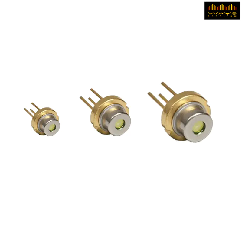
The Core Physical Mechanisms
Temperature affects a Single Mode Laser Diode through three primary physical pathways:
| Parameter | Effect of Rising Temperature | Typical Drift Rate |
|---|---|---|
| Peak Gain Wavelength | Red-shifts due to bandgap narrowing | ~0.3 – 0.5 nm/°C |
| Refractive Index | Increases, altering cavity resonance | ~1 × 10⁻⁴ /°C |
| Threshold Current | Increases exponentially (Iₜₕ ∝ exp(T/T₀)) | ~0.5 – 1.5 %/°C |
| Slope Efficiency (P/I) | Decreases due to reduced internal quantum efficiency | ~0.1 – 0.3 %/°C |
| Series Resistance | Slightly increases, affecting drive voltage | ~0.5 %/°C |
These shifts are not linear across the full operating range. For a Single Mode Laser Diode, even a ±0.5°C variation can cause a mode-hop—a sudden jump to an adjacent longitudinal mode—which destroys the single-mode purity and introduces phase discontinuities that are disastrous for coherent detection.
Why Mode-Hop Prevention Demands Active Control
A Single Mode Laser Diode maintains single-longitudinal-mode operation only when the cavity resonance aligns with the gain peak. As temperature drifts, the gain peak moves faster than the cavity mode (different temperature coefficients), causing the system to hop to the next available mode. This hop manifests as a sharp power dip and wavelength discontinuity of 0.5–1.0 nm. Wavespectrum addresses this by factory-characterizing each Single Mode Laser Diode and providing a setpoint current–temperature map that guarantees mode-hop-free operation across a defined window. Our modules include real-time temperature readback and adaptive current dithering to suppress thermal hysteresis.
Practical Performance Degradations in Real Systems
In field applications, poor temperature stability leads to:
-
Wavelength crosstalk: In DWDM systems, 0.1 nm drift can merge adjacent channels spaced at 50 GHz (~0.4 nm).
-
Power instability: A 10°C rise can drop output power by 30–40% at constant current, forcing automatic power control (APC) to overdrive the diode, accelerating aging.
-
Spectral broadening: Thermal chirp—dynamic frequency shift during pulsed operation—increases the linewidth from <1 MHz to >50 MHz, ruining heterodyne SNR.
-
Fiber coupling drift: The emission centroid shifts, reducing coupling efficiency into PM fibers by 5–15%, which directly impacts your link budget.
The table below compares performance under stabilized versus unstabilized conditions for a typical 1550 nm Single Mode Laser Diode:
| Metric | Stabilized (TEC ±0.01°C) | Unstabilized (±1°C) |
|---|---|---|
| Wavelength tolerance | ±0.02 nm | ±0.5 nm (plus mode-hops) |
| Linewidth (100 ms avg) | < 1 MHz | 5 – 20 MHz (chirp-dependent) |
| Power ripple (over 1 hr) | ±0.5 % | ±8 – 12 % |
| Polarization extinction ratio | > 23 dB | Degrades to 15 dB |
| Lifetime (est.) | > 100,000 hrs | < 20,000 hrs (due to thermal stress) |
Single Mode Laser Diode FAQ
Q1: What is the ideal temperature setpoint for a Single Mode Laser Diode to avoid mode-hops, and can I change it arbitrarily?
A1: The ideal setpoint is the temperature at which the gain peak and the nearest cavity resonance are perfectly aligned—typically between 20°C and 30°C for most commercial devices, but each unit has a unique "mode-hop-free window." Wavespectrum provides a measured mode-hop map with every Single Mode Laser Diode shipment. You cannot arbitrarily change the setpoint without re-characterizing the current–temperature phase space; arbitrary changes often push the device into a hop zone. We recommend fixing the temperature to within ±0.02°C using our matched TEC controller and using current tuning (typically 0.01 nm/mA) for fine wavelength adjustments, rather than varying the temperature.
Q2: How do I measure the real-time temperature stability of my Single Mode Laser Diode without expensive optical spectrum analyzers?
A2: A practical field method is to monitor the forward voltage (Vf) across the diode at a constant bias current, because Vf has a well-defined linear temperature coefficient (≈ –2 mV/°C for InGaAsP). Log Vf every 10 seconds and track its standard deviation. Convert that to °C using your calibration data. Additionally, Wavespectrum offers evaluation boards with built-in temperature telemetry that outputs a digital value proportional to the TEC thermistor; this allows you to correlate electrical noise with thermal oscillation. For absolute verification, a simple Fabry–Pérot etalon with a photodetector can reveal mode-hops as sudden transmission dips—no expensive OSA required.
Q3: Does pulsed operation (e.g., 1 µs pulses at 10 kHz) reduce the temperature stability requirement for a Single Mode Laser Diode compared to CW operation?
A3: No—pulsed operation actually introduces dynamic thermal chirp, because the active region heats up during the pulse (junction temperature rise) and cools between pulses. This transient temperature swing can be 3–5°C within microseconds, causing the wavelength to sweep across several GHz during the pulse itself, which broadens the effective linewidth and reduces coherent contrast. While the average temperature may be stable, the instantaneous junction temperature is not. Wavespectrum specifically recommends a lower-duty-cycle pre-pulse biasing and a faster TEC loop (with a thermal time constant < 100 ms) for pulsed applications. We also offer custom Single Mode Laser Diode packages with sub-mounts optimized for pulsed heat extraction to minimize chirp.
Best Practices for System Integration
To maximize the performance of your Single Mode Laser Diode, follow these design rules:
-
Use a PID loop with a thermistor placed as close to the die as possible—not on the submount edge. Wavespectrum modules include an integrated NTC thermistor with ±0.1°C accuracy.
-
Set the TEC current limit to at least 1.5× the steady-state requirement to handle ambient transients (e.g., air-conditioning cycles or enclosure heating).
-
Characterize the wavelength–current slope (nm/mA) at your fixed temperature; use this for fine tuning, not temperature sweeping.
-
Apply thermal paste and a large enough heat sink to keep the TEC hot-side temperature below 60°C; otherwise, the TEC’s coefficient of performance plummets.
Conclusion & Next Steps
Temperature stability is not an optional enhancement—it is the bedrock of Single Mode Laser Diode performance. From preventing destructive mode-hops to maintaining spectral purity for coherent sensing, every 0.1°C matters. Wavespectrum engineers each Single Mode Laser Diode with rigorous thermal characterization, matched TEC drivers, and application-specific submount designs, ensuring that your system achieves its full optical potential from prototype to production.
Contact us today to request thermal characterization data for your target wavelength, or to discuss our custom mounting solutions. Our application team provides full thermal model simulations and test reports before shipment—so you can design with confidence.
Ready to stabilize your optical system? Reach out to Wavespectrum now—we are here to help you choose the right Single Mode Laser Diode package, complete with thermal control recommendations and lifetime test data tailored to your operating environment.