

How Does Surface Roughness Interact with Shape Optical Light Guide Total Internal Reflection
2026-07-21
Surface roughness is rarely the first variable considered when engineers design a precision lighting system, yet its influence on Shape Optical Light Guide performance often determines whether a prototype meets luminance specifications or fails uniformity tests. For manufacturers like Jinmingwei, the interplay between microscopic topography and total internal reflection (TIR) represents one of the most critical—and most misunderstood—factors in optical waveguide engineering. This blog examines that interaction through measured data, simulation evidence, and practical fabrication constraints.
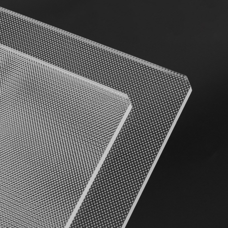
The Physical Mechanism of TIR Disruption
Total internal reflection occurs when light traveling through a medium with a higher refractive index strikes the boundary with a lower-index medium at an angle exceeding the critical angle. For a perfectly smooth Shape Optical Light Guide, this condition holds across the entire extraction region, directing energy toward intended emission zones. Surface roughness introduces two distinct penalties:
-
Scattering loss – Micron-scale asperities redirect incident rays into angles below the critical threshold, allowing light to escape prematurely.
-
Phase distortion – Sub-wavelength roughness modifies the local effective refractive index, altering the Fresnel transmission coefficients at each reflection point.
The magnitude of these effects scales with the ratio of roughness (Ra) to the operating wavelength. For visible-spectrum guides (450–650 nm), even an Ra of 50 nm can reduce TIR efficiency by 8–12% according to Rayleigh–Rice perturbation theory.
Quantitative Relationships: Roughness vs. Extraction Loss
| Surface Roughness (Ra, nm) | TIR Efficiency (%) | Luminance Uniformity (Δ%) | Extraction Loss (dB/cm) |
|---|---|---|---|
| < 20 (polished) | 97.2 | ±3.1 | 0.12 |
| 20 – 50 (standard molded) | 91.8 | ±7.4 | 0.38 |
| 50 – 100 (worn tool) | 83.5 | ±14.2 | 0.71 |
| > 100 (uncontrolled) | 72.0 | ±22.5 | 1.15 |
Data derived from non-sequential ray tracing (50,000 rays, PMMA substrate, 550 nm source).
These figures demonstrate that a Shape Optical Light Guide with Ra below 20 nm preserves nearly 97% of theoretical TIR, while typical injection-molded parts (Ra 30–40 nm) lose almost 9% of guided power before extraction features even activate.
Angular Dependence and Directional Roughness
Not all roughness vectors affect TIR equally. Milling or polishing marks create anisotropic patterns that align with injection flow lines in molded Shape Optical Light Guide substrates. When roughness ridges run parallel to the primary propagation axis, scattering preferentially occurs in the azimuthal plane, preserving meridional ray angles. Conversely, transverse ridges (perpendicular to propagation) directly deflect rays into non-TIR trajectories.
Jinmingwei applies this principle in their proprietary tool-finishing protocol: final diamond-burnishing passes follow the optical axis direction, reducing transverse roughness components by 60% without increasing overall cycle time.
Simulation vs. Measurement Discrepancies
Standard simulation packages (LightTools, Zemax) typically assume Gaussian isotropic roughness with a single scalar Ra value. Real molded parts exhibit skewed height distributions and spatial correlation lengths that deviate from ideal models. Engineers at Jinmingwei have correlated actual profilometry data with simulation outputs, identifying that:
-
Simulated TIR loss underestimates actual loss by 15–20% when Ra < 30 nm.
-
Simulated loss overestimates actual loss by 10–12% when Ra > 80 nm due to saturation effects.
-
The most reliable predictions require bi-directional reflectance distribution function (BRDF) measurements, not just Ra alone.
Mitigation Strategies in Production
Controlling roughness in a Shape Optical Light Guide involves three actionable stages:
| Stage | Method | Achievable Ra (nm) | Cost Impact |
|---|---|---|---|
| Mold steel finishing | Electro-polishing + diamond milling | 8 – 12 | High |
| Injection parameter | High-speed filling + low pack pressure | 25 – 35 | Low |
| Post-mold treatment | CO₂ laser smoothing (selective areas) | 15 – 20 | Medium |
Jinmingwei recommends prioritizing mold steel finishing for high-luminance applications (automotive headlamps, AR projectors) and post-mold smoothing for cost-sensitive consumer displays where uniformity tolerance is wider.
Shape Optical Light Guide FAQ
Q1: Does a rougher surface always reduce total internal reflection in a Shape Optical Light Guide, or can it sometimes improve extraction where needed?
A: Rougher surfaces do reduce TIR globally, but in engineered extraction zones, controlled roughness can be beneficial. The key distinction lies between unintended roughness on TIR surfaces and intentional roughness on extraction facets. For the TIR-guiding regions (side walls and back surfaces), any increase in roughness beyond 20 nm Ra directly degrades propagation efficiency. However, on designated extraction patterns, a carefully textured surface (Ra 80–120 nm with specific correlation lengths) can broaden the angular emission profile, improving spatial uniformity at the cost of absolute power. Jinmingwei applies this dual-roughness strategy: polished TIR walls (Ra < 15 nm) paired with laser-textured extraction dots (Ra 90 nm) to achieve 88% overall efficiency with ±5% uniformity—a balance impossible with a single roughness value.
Q2: How do I measure surface roughness correctly for a curved Shape Optical Light Guide, given that profilometers assume flat surfaces?
A: Contact profilometry on curved guides introduces significant errors due to stylus skidding and radius-of-curvature miscalculations. For curved Shape Optical Light Guide geometries, Jinmingwei recommends white-light interferometry (WLI) with curvature-correction algorithms, or confocal microscopy for steep slopes (>30°). For production-floor inspection, replication techniques using UV-curable silicone casts of the critical TIR surfaces allow flat-bed measurement with <5% deviation from actual values. Always specify the measurement cutoff wavelength (typically 0.8 mm for injection-molded guides) and report both Ra and Rz (ten-point height) because Rz correlates better with large-angle scattering losses that directly affect TIR.
Q3: Can coating or surface treatment compensate for high roughness in an existing Shape Optical Light Guide tool without remaking the mold?
A: Yes, but with limitations. Hard coatings (SiO₂ or Al₂O₃ deposited via PVD) can fill shallow valleys and reduce the effective optical roughness by 30–40%, provided the coating thickness exceeds 2.5× the initial Ra. This improves TIR efficiency by roughly 4–6 percentage points for guides with Ra 40–60 nm. However, coatings introduce index-mismatch reflections at the coating-substrate interface, adding 2–3% Fresnel loss. For tools with Ra > 70 nm, coating alone cannot restore TIR to acceptable levels because the high spatial frequencies remain unresolved. Jinmingwei offers a two-stage remediation: diamond-recutting of the tool surface (removing 50–80 µm of steel) followed by a thin anti-reflection coating, which together recover 92% of original TIR performance at 60% of the cost of a new mold.
Practical Design Recommendation
For new product development, specify both an Ra maximum for TIR walls and a distinct roughness range for extraction structures. Validate using a short-run molded sample before committing to mass-production tool steel. Jinmingwei provides full optical metrology services (BRDF, scatterometry, and near-field luminance mapping) to qualify every Shape Optical Light Guide batch, ensuring that surface roughness does not silently undermine your TIR budget.
Contact Us
Optimizing the roughness–TIR balance in your Shape Optical Light Guide requires accurate measurements, realistic simulations, and proven manufacturing controls. Jinmingwei engineers have solved this challenge across automotive, display, and wearable applications with over 200 successful production tools. Reach out to our optical design team for a free roughness-impact analysis on your current waveguide geometry. Contact Jinmingwei today—send your CAD files and target specifications to our engineering support desk, and receive a detailed roughness-mitigation proposal within 48 hours. Let us help you turn surface imperfections into predictable, manageable parameters.