

How Does Rigid-Flex PCB Work?
2026-04-02
Summary: Rigid-Flex PCBs combine the strengths of rigid and flexible circuits, allowing advanced electronic designs that save space, enhance reliability, and optimize performance. This article explores how Rigid-Flex PCBs function, their advantages, applications, design considerations, and how HONTEC can support your project needs.
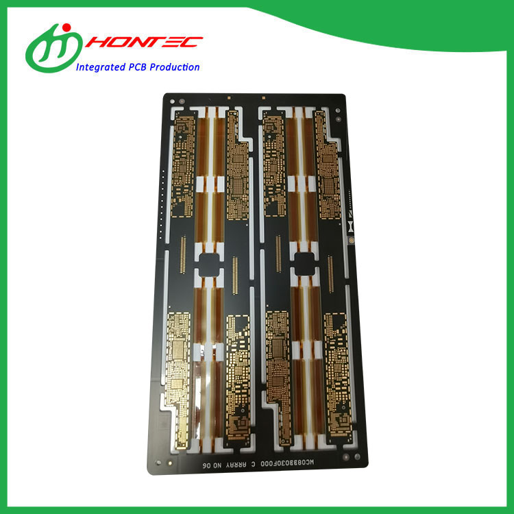
Table of Contents
Introduction to Rigid-Flex PCB
Rigid-Flex PCB is a hybrid circuit combining both rigid and flexible substrates. This innovative technology is widely used in industries where space optimization, mechanical flexibility, and reliability are critical. Unlike traditional PCBs, which are either fully rigid or fully flexible, Rigid-Flex PCBs provide the best of both worlds. They are particularly beneficial for modern compact electronic devices.
HONTEC specializes in designing and manufacturing high-quality Rigid-Flex PCBs that meet the most demanding specifications, ensuring exceptional durability and performance for your products.
Structure and Components
A typical Rigid-Flex PCB consists of several layers strategically stacked to achieve both mechanical rigidity and flexibility. Below is a simplified representation:
| Layer | Function |
|---|---|
| Rigid Layer | Provides mechanical strength and stable mounting for components. |
| Flexible Layer | Allows bending, twisting, and folding to save space and connect complex layouts. |
| Copper Traces | Conducts electrical signals between components. |
| Polyimide/FR4 Material | Serves as insulation and base for both flexible and rigid areas. |
| Coverlay/Soldermask | Protects the circuitry from environmental and mechanical damage. |
The combination of these layers ensures Rigid-Flex PCBs maintain structural integrity while allowing flexibility in specific sections.
Key Advantages of Rigid-Flex PCBs
- Space-saving: Reduces the need for connectors and cables, enabling compact designs.
- Enhanced Reliability: Flexible areas reduce stress on solder joints and prevent breakage.
- Lightweight: Combines materials efficiently to reduce overall weight in portable devices.
- Improved Signal Integrity: Minimizes electrical interference through optimized trace routing.
- Durability: Designed to withstand repeated bending and thermal cycling.
Applications Across Industries
Rigid-Flex PCBs are widely used in industries that require innovative and compact electronic designs. Common applications include:
- Consumer Electronics: Smartphones, tablets, wearables.
- Medical Devices: Portable diagnostic equipment, implantable devices.
- Aerospace & Defense: Avionics, satellite systems, military-grade electronics.
- Automotive: Advanced driver-assistance systems (ADAS), dashboard electronics.
- Industrial Equipment: Robotics, industrial sensors, and control units.
Design Considerations
Designing a Rigid-Flex PCB requires careful planning to maximize functionality while avoiding mechanical and electrical failures. Key considerations include:
- Flex Region Placement: Identify areas that need bending and avoid placing heavy components on them.
- Layer Stack-up: Determine the number of rigid and flexible layers to optimize space and signal routing.
- Material Selection: Polyimide for flexible areas, FR4 for rigid areas, and suitable copper thickness for current requirements.
- Thermal Management: Include vias and thermal reliefs to prevent overheating in high-power sections.
- Mechanical Stress Analysis: Simulate bending to prevent fractures and maintain reliability over the product's lifecycle.
Manufacturing Process
HONTEC’s manufacturing of Rigid-Flex PCBs involves a multi-step process ensuring precision and reliability:
- Material Preparation: Prepares flexible and rigid substrates with precise dimensions.
- Layer Lamination: Combines rigid and flexible layers using heat and pressure.
- Photoresist & Etching: Defines copper traces and removes excess material.
- Drilling & Plating: Creates vias and connects multiple layers electrically.
- Assembly & Testing: Components are mounted, and the final board is tested for electrical integrity and mechanical durability.
Troubleshooting and Maintenance
Common issues with Rigid-Flex PCBs include delamination, broken traces, and thermal fatigue. Troubleshooting involves:
- Visual inspection for visible cracks or broken traces.
- Electrical testing to detect shorts or open circuits.
- Stress testing by bending the flexible areas carefully.
- Preventive maintenance, such as avoiding repeated bending beyond design limits.
Frequently Asked Questions
Q1: Can Rigid-Flex PCBs be used in high-temperature environments?
A1: Yes, when designed with suitable materials like polyimide and reinforced copper layers, they can tolerate high temperatures.
Q2: How much bending can a flexible section handle?
A2: The bending radius and number of cycles depend on the material and design. HONTEC provides precise guidelines for each project.
Q3: Are Rigid-Flex PCBs more expensive than traditional PCBs?
A3: They are generally more costly due to complex manufacturing, but the benefits in reliability, space-saving, and performance often justify the investment.
Q4: How do I get a quote for a Rigid-Flex PCB from HONTEC?
A4: Visit our product page here and submit your design requirements for a detailed quote.
Ready to optimize your electronic designs with high-quality Rigid-Flex PCBs? Contact us today and let HONTEC help bring your project to life!