

How Does a Variable Frequency Drive Filter Help Reduce EMI and Bearing Currents
2026-10-22
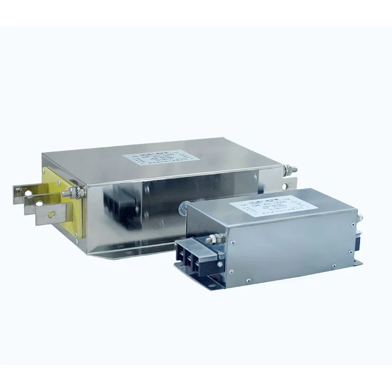
Modern industrial drives run faster, switch harder, and operate on longer cables than ever before. Those conditions create two persistent problems—electromagnetic interference and shaft voltage discharge—that quietly damage motors and disrupt nearby equipment. A Variable Frequency Drive Filter from Dufew addresses both at the source, suppressing high-frequency noise before it leaves the drive cabinet and limiting the common-mode voltage that drives bearing currents. This article explains the mechanisms, the filter types, and the selection criteria that matter in real installations.
The Two Problems a VFD Creates
A standard PWM drive switches IGBTs at 2–16 kHz with dv/dt values that can exceed 5,000 V/µs. Two consequences follow:
-
High-frequency EMI travels along motor cables and radiates into sensitive circuits, causing sensor faults, encoder errors, and communication dropouts.
-
Common-mode voltage charges the motor shaft through capacitive coupling in the stator. When the shaft voltage exceeds the breakdown threshold of the bearing grease film, a discharge current flows through the bearing, eroding raceways over time (electrical discharge machining, or EDM).
How a Variable Frequency Drive Filter Reduces EMI
A Variable Frequency Drive Filter provides a low-impedance return path for high-frequency currents and shapes the output waveform.
| Filter Type | Primary Mechanism | EMI Benefit |
|---|---|---|
| dv/dt filter | Limits voltage rise time to typically <500 V/µs | Reduces radiated emissions and cable stress |
| Sine wave filter | Reconstructs a near-sinusoidal output | Near-eliminates PWM carrier emissions on long cables |
| Common-mode choke | Increases impedance to common-mode current | Suppresses ground leakage and conducted EMI |
| EMC/EMI input filter | Attenuates conducted noise toward the supply | Meets CISPR 11 / EN 61800-3 limits |
Key EMI reduction mechanisms:
-
Slower edge rates reduce the harmonic content of the output voltage, lowering both conducted and radiated emissions.
-
Common-mode impedance blocks the return path that couples noise onto grounding systems and adjacent cabling.
-
Shielded cable termination at the filter enclosure keeps high-frequency current inside the defined path rather than the plant ground grid.
-
Reduced cable charging current on long runs prevents resonance amplification that worsens emissions.
How a Variable Frequency Drive Filter Reduces Bearing Currents
Bearing currents originate from common-mode voltage, so any device that limits that voltage directly protects the bearing.
-
Common-mode voltage reduction: A Dufew common-mode filter lowers the peak shaft voltage below the grease film breakdown threshold, preventing discharge events.
-
dv/dt limitation: Slower switching edges reduce the capacitive coupling current injected into the shaft.
-
Sine wave output: With a near-sinusoidal waveform, common-mode voltage is substantially lower and bearing current magnitudes drop accordingly.
-
System-level effect: Combined with proper grounding and shielded cable, filter installation typically reduces shaft voltage from tens of volts to single digits.
| Mitigation Measure | Shaft Voltage Reduction | Bearing Current Reduction | Best Applied To |
|---|---|---|---|
| dv/dt filter | Moderate | Moderate | Medium cables, standard motors |
| Sine wave filter | High | High | Long cables, older or non-inverter-duty motors |
| Common-mode choke | High | High | Retrofit and multi-drive systems |
| Shaft grounding ring | None (diverts current) | High | Large motors, critical assets |
Selection and Installation Checklist
-
Match filter current rating to motor full-load current, not drive nameplate alone.
-
Confirm the maximum cable length the filter supports; sine wave filters typically allow far longer runs.
-
Verify switching frequency compatibility—some sine wave filters require derating above 4 kHz.
-
Mount the filter as close to the drive output as possible and bond it to the enclosure with low-impedance connections.
-
Use symmetrical, shielded motor cable with 360° termination at both ends.
-
Confirm compliance targets against EN 61800-3 category C2 or C3 as required by the site.
Frequently Asked Questions
Q: Does a Variable Frequency Drive Filter eliminate bearing currents completely?
A: No single device guarantees complete elimination, but a properly selected Variable Frequency Drive Filter combined with shielded cable, correct grounding, and a shaft grounding ring reduces bearing current to levels that effectively prevent EDM damage in most industrial applications.
Q: How do I know whether I need a dv/dt filter or a sine wave filter?
A: Choose a dv/dt filter when cable runs are moderate and the motor is inverter-duty rated; choose a sine wave filter when cables exceed roughly 100 meters, when the motor is not inverter-duty rated, or when audible noise and carrier emissions must be minimized.
Q: Can a Variable Frequency Drive Filter improve power quality on the supply side?
A: Output-side filters address motor cable and bearing issues, while input-side EMC and harmonic filters address supply-side power quality; for complete protection, specify both an output filter and an input EMC filter matched to the drive rating and the applicable EN 61800-3 category.
Conclusion
EMI and bearing currents share a common origin: the fast switching and common-mode voltage inherent to PWM drives. A correctly specified Variable Frequency Drive Filter attacks both at the source, protecting motors, cables, and nearby electronics while supporting regulatory compliance. Dufew engineers can review your drive rating, cable length, and grounding scheme to recommend the right filter configuration for your application.
Contact us today to discuss your Variable Frequency Drive Filter requirements and request a selection review for your next project.