

How Does a Dev Kit Carrier Board Maximize Development Efficiency?
2026-03-05
Article Summary
A Dev Kit Carrier Board is a pivotal hardware component for embedded systems developers, enabling connectivity, expansion, and rapid prototyping when paired with processor modules or System-on-Modules (SoMs). This article clarifies what carrier boards are, why they matter, how to select the right one for your project, and how to avoid common pitfalls that slow development cycles. By the end, readers will understand carrier board features, performance criteria, compatibility challenges, and how Thinkcore’s Dev Kit Carrier Boards support streamlined development workflows for industrial, IoT, robotics, and edge computing applications.
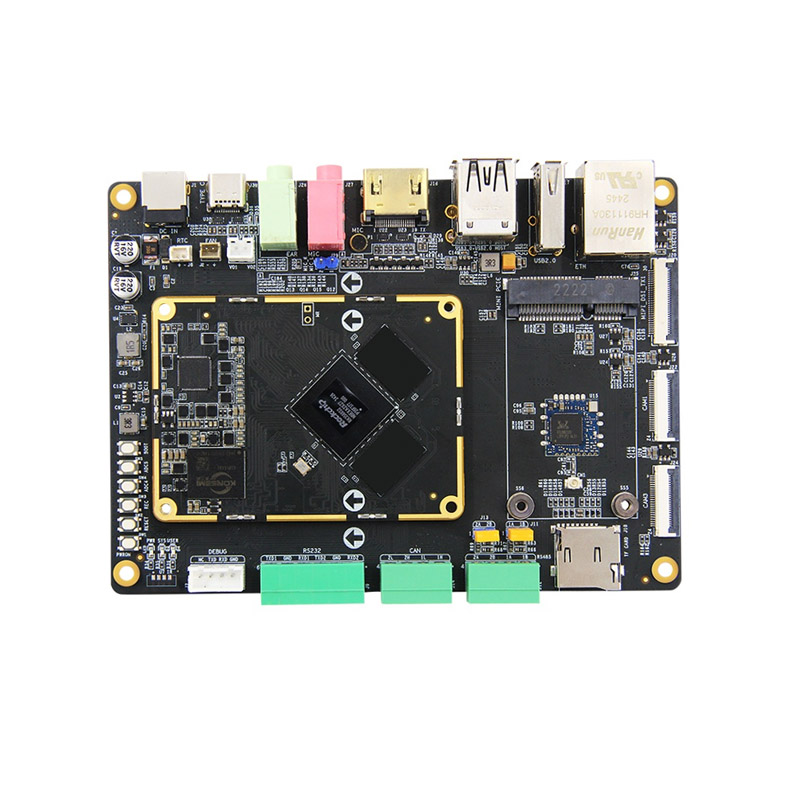
Table of Contents
- Introduction to Dev Kit Carrier Boards
- Common Developer Pain Points
- Key Components and Interfaces
- Guide to Choosing the Right Board
- Dev Kit Carrier Board Comparison Table
- Module Integration and Compatibility
- Best Practices for Deployment
- Frequently Asked Questions
- Conclusion and Contact Us
Introduction to Dev Kit Carrier Boards
A Dev Kit Carrier Board functions as the backbone of a development platform by providing power distribution, I/O interfaces, communication ports, and expansion connectors necessary for testing and deploying embedded applications. Carrier boards are engineered to connect directly to a compute module, such as an ARM®-based processor, enabling developers to access peripherals without custom PCB design during early development stages.
Thinkcore Dev Kit Carrier Boards are designed to accelerate development cycles by offering robust connectivity, standardized interfaces, and flexibility for prototyping across a wide range of industries. These boards help reduce time to first test and allow developers to focus on software logic, system integration, and performance tuning.
Common Developer Pain Points
Embedded system developers often encounter similar challenges when selecting or using carrier boards. Addressing these pain points early can prevent costly redesigns or delays.
- Compatibility Mismatches – Carrier boards that do not match module pinouts or power requirements cause integration delays.
- Insufficient I/O or Expansion – Limited interfaces force engineers to create ad-hoc solutions or redesign board layouts.
- Poor Documentation – Incomplete schematics, unclear reference designs, or missing software drivers slow debugging.
- Thermal and Power Issues – Improper power regulation or heat dissipation impacts system stability during testing.
- Non-Scalable Designs – Prototypes that cannot transition to production form factors increase engineering overhead.
Understanding these pain points helps developers identify features critical to successful project outcomes.
Key Components and Interfaces
Carrier boards consist of several functional blocks that deliver connectivity and system control. The following list outlines the essential elements developers should consider.
- Power Management – Voltage regulation, power sequencing, and protection circuitry to support modules and peripherals.
- Processor Expansion Socket – Standardized connector to attach compute modules or SoMs.
- Communication Interfaces – USB, Ethernet, UART, I2C, SPI, CAN, and other buses for external connectivity.
- Display and Multimedia Ports – HDMI, MIPI-DSI, and LVDS connectors for visual output.
- Storage Interfaces – eMMC, SD card slots, and SATA connectors for persistent data storage.
- Debug and Programming Headers – JTAG, SWD, or UART headers for firmware debugging and programming.
Guide to Choosing the Right Board
Selecting a carrier board should be a structured decision based on project requirements, hardware compatibility, and long-term goals. Consider the following criteria:
- Module Support – Ensure the board supports the exact processor module you plan to use.
- Required Interfaces – Match the board’s I/O with sensors, actuators, displays, and networking needs.
- Power Budget – Evaluate power supply ratings and efficiency for all connected peripherals.
- Thermal Management – Boards with integrated heatsinks or thermal pads help maintain reliability under load.
- Form Factor – Size constraints and mounting options influence enclosure design and deployment.
- Documentation and Support – Verified schematics, BOMs, and sample code accelerate development.
Thinkcore provides detailed datasheets, reference schematics, and breakout maps to help engineers evaluate compatibility and avoid integration issues early.
Dev Kit Carrier Board Comparison Table
| Feature | Standard Board A | Advanced Board B | Thinkcore Dev Kit Carrier Board |
|---|---|---|---|
| Processor Module Support | Limited SoM Compatibility | Moderate SoM Compatibility | Wide SoM and ARM Module Support |
| Ethernet Interfaces | 1 × 10/100 | 2 × 10/100/1000 | 2 × Gigabit + Optional PoE |
| USB Ports | 2 × USB 2.0 | 4 × USB (2.0 + 3.0) | Multiple USB 3.x + USB-C Options |
| Display Support | No | Single HDMI | HDMI, MIPI-DSI, LVDS Support |
| Debug Headers | Basic | Standard | Full JTAG/SWD Integration |
Module Integration and Compatibility
Successful integration of a compute module with a carrier board depends on pinout alignment, power rail matching, and signal integrity. Modules may expose high-speed interfaces that require careful routing and termination, which professionally designed carrier boards address during manufacturing.
Thinkcore’s Dev Kit Carrier Boards include standardized connectors and test points to support rapid attachment of processor modules and immediate access to critical system functions. This accelerates firmware bring-up, enables faster driver integration, and improves first-pass success rates during initial hardware validation.
Best Practices for Deployment
Deploying a carrier board effectively requires adherence to engineering best practices. Key considerations include:
- Verify Pinout Documentation – Check alignment between the carrier board and compute module datasheets.
- Perform Power Sequencing Tests – Verify correct startup and shutdown behaviors.
- Test Interfaces Individually – Validate network, storage, and peripheral connections early.
- Monitor Thermal Load – Use heat dissipation strategies during prolonged testing.
- Iterate Firmware Safely – Use dedicated debug headers for incremental updates without system resets.
Frequently Asked Questions
What is the primary purpose of a Dev Kit Carrier Board?
A carrier board enables a compute module to interface with external hardware and peripherals for prototyping, testing, and early deployment.
Can any module work with any carrier board?
No. Compatibility depends on matching pinouts, power requirements, and supported interfaces between the module and carrier board.
Why is documentation important?
Clear schematics and interface maps reduce guesswork, help with debugging, and speed up development.
Do carrier boards support production deployment?
Some carrier boards are engineered for both prototyping and low-volume production, but many teams transition to custom board designs for mass production.
How does Thinkcore support board selection?
Thinkcore provides comprehensive datasheets, interface maps, and technical support to help engineers align carrier boards with project requirements.
Conclusion and Contact Us
Dev Kit Carrier Boards are essential tools for embedded systems development teams looking to shorten development cycles, improve integration reliability, and access a broad range of interfaces without custom PCB design. Understanding how carrier boards function and what criteria matter most helps engineers avoid common pitfalls and deploy solutions faster.
Thinkcore offers powerful Dev Kit Carrier Boards tailored for scalability, performance, and flexibility across embedded applications. Whether you are building industrial automation, edge computing systems, robotic controllers, or IoT devices, our solutions help you get to prototype and production with confidence. To discuss your specific hardware requirements, get expert advice, or learn more about our Dev Kit Carrier Board offerings, contact us today and let Thinkcore support your next project.