

How Do You Wire a Magnetic Motor Starter Switch Correctly
2026-01-27
Properly wiring a Magnetic Motor Starter Switch is fundamental to ensuring the safety, reliability, and longevity of industrial motor-driven equipment. Incorrect installation can lead to motor failure, safety hazards, and operational downtime. This guide, leveraging SPX's expertise in electrical components, outlines the correct procedure, emphasizing safety and adherence to standards.
Before beginning any work, ensure the power supply is completely locked out and tagged out (LOTO). Verify this with a multimeter. You will typically need:
-
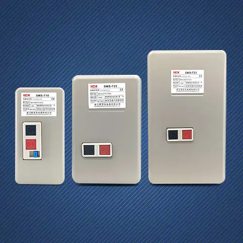
The Magnetic Motor Starter Switch unit (including contactor and overload relay)
-
Appropriate gauge power and control wiring
-
Wire strippers, ferrules, and screwdrivers
-
A wiring diagram specific to your SPX starter model
The wiring process involves two main circuits:
1. The Power Circuit
This carries the main current to the motor. Connect the line power (L1, L2, L3) to the designated line terminals on the contactor. Then, run wires from the load terminals (T1, T2, T3) of the contactor, through the thermal overload relay, and finally to the motor terminals.
2. The Control Circuit
This circuit controls the operation of the magnetic coil. It is typically lower voltage (e.g., 24V AC/DC or 120V). A basic start/stop station wiring is as follows:
| Component | Connection Point |
|---|---|
| Power Source (Hot) | -> Stop Button (NC) |
| Stop Button (NC) | -> Start Button (NO) |
| Start Button (NO) | -> Coil (A1) & Auxiliary Contact (NO) |
| Auxiliary Contact (NO) | -> Coil (A1) |
| Coil (A2) | -> Power Source (Neutral) |
When the Start button is pressed, it energizes the coil, closing the main power contacts and the auxiliary "holding" contact, which keeps the circuit latched after the Start button is released.
Magnetic Motor Starter Switch FAQ
What is the purpose of the overload relay in a Magnetic Motor Starter Switch?
The overload relay protects the motor from drawing excessive current over time, which causes overheating. It monitors the current flowing to the motor and will trip the control circuit, de-energizing the coil and stopping the motor, if a sustained overload condition is detected.
Why does my Magnetic Motor Starter Switch hum loudly when energized?
A loud hum often indicates a problem with the magnetic coil or armature. This could be due to a weak coil holding circuit, dirt/debris preventing the armature from sealing properly against the electromagnet, or a shading coil failure that prevents smooth AC magnetization. An SPX technician can diagnose the exact cause.
Can I use a three-phase Magnetic Motor Starter Switch for a single-phase motor?
While physically possible, it is generally inefficient and may not provide proper single-phase overload protection. One phase of the overload relay may need to be bypassed or jumpered, compromising protection. It is always recommended to use a starter designed and rated for the specific motor phase.
Proper wiring is the first step toward a safe and efficient system. For complex installations or when in doubt, always consult a qualified electrician and refer to the specific manual for your SPX Magnetic Motor Starter Switch model.
Need a reliable component for your critical application? Contact us today to explore the robust and certified range of SPX Magnetic Motor Starter Switch solutions and get expert support for your project.