

How Do Automotive Relays Handle Inrush Current from Capacitive LED Lighting Loads?
2026-09-10
1. What Makes Capacitive LED Lighting Loads Different from Halogen or Incandescent Loads?
A halogen bulb is a resistive load. Its current draw is proportional to the applied voltage. When the relay contacts close, the current rises smoothly to its steady-state value. A halogen bulb drawing 55W at 12V draws about 4.6A steady-state, with an inrush current of perhaps 8A for a few milliseconds. An LED headlight assembly contains a driver circuit with a capacitor bank on the input side. When the relay contacts close, the discharged capacitors act as a near short circuit. The inrush current is limited only by the wiring resistance and the capacitor ESR. This inrush can reach 100A or more for a duration of 100 to 500 microseconds. The steady-state current is lower than the halogen bulb it replaces—perhaps 2.5A—but the peak current is 20 times higher.
The failure mechanism: When the relay contacts close on a capacitive load, the high inrush current flows through the microscopic contact points that touch first. The energy dissipated at those points melts the contact material, causing micro-welding. Over repeated cycles, the welded area grows until the contacts stick closed permanently.
In our factory, we have tested Automotive Relays with both resistive and capacitive loads at the same steady-state current. The capacitive load caused contact welding in 5,000 cycles, while the resistive load showed no degradation after 100,000 cycles. This is why relay selection for LED lighting requires a different approach than for traditional lighting.
2. What Relay Design Features Mitigate Capacitive Inrush Current?
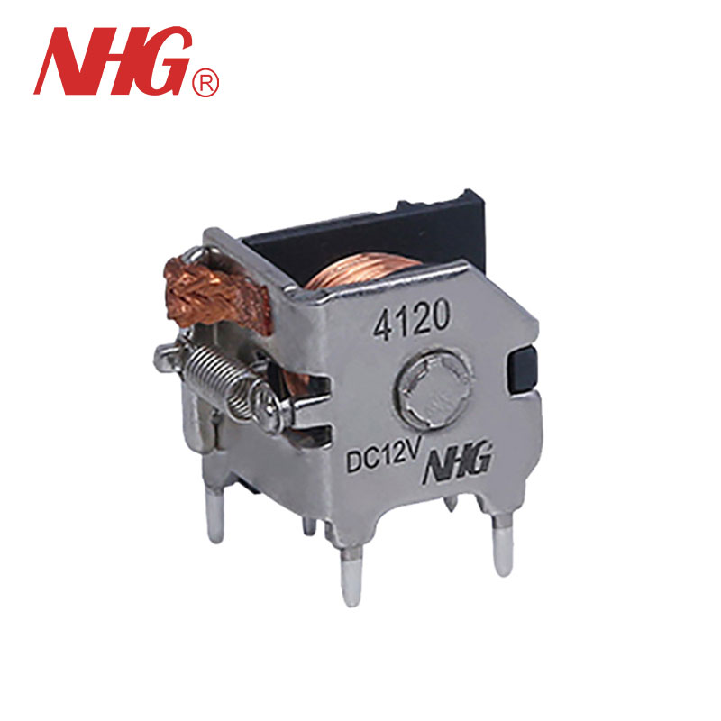
Not all Automotive Relays are equally suited to capacitive loads. The key design features that improve performance are contact material, contact force, and contact gap. Silver tin oxide contacts are more resistant to welding than silver nickel contacts because the tin oxide particles disperse the molten metal and prevent a continuous weld. Higher contact force increases the contact area and reduces the current density at the contact points. A larger contact gap reduces the probability of arc restrike after the contacts open. The table below compares the performance of different relay designs under capacitive LED load conditions.
| Relay design feature | Standard relay (silver nickel) | LED-optimized relay (silver tin oxide) | Improvement |
| Contact material | AgNi (silver nickel) | AgSnO2 (silver tin oxide) | Higher resistance to welding |
| Contact force | 0.5 – 0.8 N | 1.0 – 1.5 N | Larger contact area, lower current density |
| Contact gap | 0.25 mm | 0.40 mm | Reduced arc restrike probability |
| Inrush current rating | 50A for 10 ms | 120A for 10 ms | Handles capacitive inrush |
| Cycle life with capacitive load (100A inrush, 2.5A steady) | 10,000 cycles | 100,000 cycles | 10x improvement |
Ningbo Huaguan Electronics Co., Ltd. manufactures Automotive Relays with silver tin oxide contacts that are specifically designed for capacitive loads. Our relays are tested with a simulated LED load that produces a 100A inrush current for 300 microseconds. We verify that the contact resistance remains within specification after 100,000 cycles.
3. What Circuit Design Strategies Reduce Inrush Current to the Relay Contacts?
Relay selection is only half of the solution. The circuit design can also reduce the inrush current that the relay must handle. There are three practical strategies. The first is to add a pre-charge resistor in series with the relay contacts. The resistor limits the initial current while the capacitors charge, and then a second relay contact shorts out the resistor. The second is to use a relay with a normally closed contact that connects a low-value resistor across the LED driver input. The third is to select an LED driver that has a soft-start feature, which limits the inrush current at the driver level. The table below compares these strategies.
| Strategy | Method | Inrush reduction | Cost impact | Complexity |
| Pre-charge resistor | Series resistor bypassed by second contact | 80 – 90% | Low ($0.50) | Moderate |
| Soft-start LED driver | Driver with built-in current limiting | 90 – 95% | Medium ($2 – $5) | Low (selection only) |
| RC snubber across contacts | Resistor-capacitor network | 30 – 50% | Low ($0.30) | Low |
For most vehicle lighting applications, the most practical solution is to specify an LED driver with soft-start capability. If that is not possible, a pre-charge resistor provides a robust solution. Our factory provides application support to help customers select the right combination of relay and circuit design.
4. How Do You Validate That a Relay Will Survive the Actual Load Conditions?
Validation requires testing the relay with the actual load, not with a resistive load bank. The test should measure the inrush current waveform, the contact resistance after cycling, and the contact temperature during operation. The standard test for Automotive Relays is defined in IEC 61810-1, but for capacitive loads, the test conditions must be adjusted. The test should use a capacitor bank that matches the LED driver input capacitance, and the test should cycle the relay at the expected rate. In our factory, we use a programmable load that simulates the exact inrush waveform of the customer's LED driver. We record the contact resistance every 10,000 cycles and stop the test when the resistance exceeds 100 milliohms or when welding occurs. This data allows us to predict the relay life under actual operating conditions.
Frequently Asked Questions About Automotive Relays and Capacitive LED Loads
Summary for Vehicle Electrical Engineers
Capacitive LED lighting loads present a unique challenge for Automotive Relays. The high inrush current, caused by the capacitor bank in the LED driver, can weld contacts and shorten relay life. The solution requires both the right relay design—silver tin oxide contacts, higher contact force, larger contact gap—and the right circuit design—soft-start drivers or pre-charge resistors. Validation testing with the actual load waveform is essential to confirm that the relay will survive the expected number of cycles. Our factory has developed a range of Automotive Relays that are optimized for LED lighting applications.
Ningbo Huaguan Electronics Co., Ltd. manufactures Automotive Relays with silver tin oxide contacts for capacitive loads. We provide full inrush current testing and application support. Our relays are used by vehicle manufacturers and aftermarket lighting suppliers worldwide.