

How Do Automotive Relays Control Engine Cooling Fans in Modern Vehicles?
2026-09-02
Imagine driving through a busy city on a sweltering summer afternoon. Your engine is working hard, and the temperature gauge starts to climb. Suddenly, you hear a faint click from under the hood, followed by the whir of a powerful fan engaging. The temperature needle begins to drop, and your engine stays safe. This silent, seamless process is orchestrated by a small but mighty component: the Automotive Relay. Without it, the cooling fan would either run constantly, draining energy and wearing out prematurely, or fail to engage when needed, leading to engine overheating and potentially catastrophic damage. The Automotive Relay is the unsung hero of your vehicle's thermal management system.
In modern vehicles, the engine cooling fan is no longer a simple on/off device. It is a sophisticated, variable-speed system that responds to a multitude of inputs: engine temperature, vehicle speed, air conditioning load, and even coolant pressure. At the heart of this intelligent control system lies the Automotive Relay, which acts as a high-current switch, enabling the Engine Control Unit (ECU) to control the fan's power supply with precision. This article will dissect the inner workings of this system, exploring the role of the Automotive Relay in controlling fan speed, protecting the electrical system, and ensuring reliable operation under all driving conditions. We will also explore the future of fan control, from smart relays with integrated diagnostics to the transition to solid-state technology. Whether you are an automotive engineer, a technician, or simply a curious driver, this article will provide you with a comprehensive understanding of how Automotive Relays control engine cooling fans in modern vehicles.
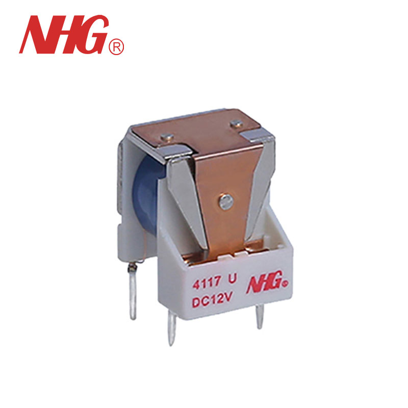
Table of Contents
- 1. What Is an Automotive Relay and How Does It Work?
- 2. Why Is a Relay Necessary for Cooling Fan Control?
- 3. How Does the ECU Use Relays to Turn the Fan On and Off?
- 4. How Do Relays Enable Variable-Speed Fan Control?
- 5. What Are the Key Technical Specifications of Cooling Fan Relays?
- 6. How Are Relays Evolving with Smart and Solid-State Technology?
- 7. Frequently Asked Questions (FAQ)
- 8. Conclusion
1. What Is an Automotive Relay and How Does It Work?
Before exploring the specific application of Automotive Relays in cooling fan control, it is helpful to understand what an automotive relay is and how it operates. At its most basic level, an Automotive Relay is an electrically operated switch. It uses a small electrical current to control a larger current. This is the key principle: a low-current signal from the ECU controls a high-current circuit that powers the cooling fan motor. The relay itself consists of an electromagnet (a coil of wire), a movable armature, and a set of contacts. When a small current flows through the coil, it creates a magnetic field that attracts the armature. The armature then moves, closing a set of contacts that complete the high-current circuit, thereby allowing power to flow to the fan.
Think of an Automotive Relay as a remote-controlled switch. You press a small button (the ECU signal), and a larger switch (the relay) is activated, turning on a high-powered device (the fan). This simple principle has two critical advantages: it allows the ECU to control high-power devices without having to handle the high currents itself (which would require very thick and expensive wiring), and it allows the ECU to switch the fan on and off quickly and reliably. The relay is typically housed in a small plastic enclosure, with terminals for the coil (control circuit) and the contacts (load circuit). The contacts are designed to handle the high inrush currents associated with starting an electric motor, which can be several times the motor's normal running current.
At Ningbo Huaguan Electronics Co., Ltd., we manufacture a range of Automotive Relays specifically designed for the demanding automotive environment. Our relays are engineered to withstand high temperatures, vibration, and moisture, ensuring reliable operation over the vehicle's lifespan. The contacts are made from a high-performance alloy that resists welding and pitting, and the coil is designed to operate efficiently at the standard automotive voltage of 12V or 24V. Understanding the anatomy of an Automotive Relay is the first step in understanding its crucial role in cooling fan control.
2. Why Is a Relay Necessary for Cooling Fan Control?
To appreciate the role of an Automotive Relay in cooling fan control, it's helpful to understand the electrical demands of a typical engine cooling fan. A modern cooling fan can draw 15 to 30 amperes or more, particularly during high-demand conditions like stop-and-go traffic on a hot day. This is a significant amount of current, and it cannot be directly handled by the Engine Control Unit (ECU). The ECU's internal electronics are designed for low-current, high-speed logic, not for driving high-current motors. Connecting a cooling fan directly to the ECU would damage its delicate components and would require impractically thick wiring and heavy connectors.
Imagine a scenario where the cooling fan is directly controlled by a switch on the dashboard. The switch would need to be rated for 30 amps, which would be large, expensive, and prone to arcing and failure. The wiring from the switch to the fan would need to be very thick to handle the current, adding weight and cost. By placing an Automotive Relay between the switch (or the ECU) and the fan, the problem is elegantly solved. The switch (or ECU) only needs to handle a small current (typically less than 1 amp) to energize the relay coil. The relay then handles the high current of the fan motor. This allows the use of smaller, lighter wiring for the control circuit, and a shorter, more robust wiring path for the high-current circuit.
The Automotive Relay also provides electrical isolation between the control circuit (the ECU) and the load circuit (the fan). This protection is essential because the fan motor can generate electrical noise (voltage spikes) as it operates. These spikes, if allowed to travel back to the ECU, could interfere with its operation or even damage its sensitive electronics. The relay's physical separation and electromagnetic design help to isolate these noise sources, protecting the ECU and ensuring reliable system operation. For a system as critical as engine cooling, this isolation is a non-negotiable design feature. Our factory at Huaguan has refined the design of our Automotive Relays to provide robust isolation and reliable switching, ensuring that the fan operates as intended without interfering with the ECU or other sensitive vehicle electronics.
3. How Does the ECU Use Relays to Turn the Fan On and Off?
The simplest level of fan control is on/off switching. In this mode, the ECU determines when the cooling fan needs to be turned on and when it can be turned off, based on the engine temperature and other inputs. The ECU uses a temperature sensor (typically a thermistor) to measure the engine coolant temperature. When the temperature exceeds a predetermined threshold (often around 90-100°C), the ECU outputs a control signal to energize the Automotive Relay coil, closing the relay contacts and turning the fan on. When the temperature drops below a second threshold (often around 85-90°C), the ECU de-energizes the relay, opening the contacts and turning the fan off.
This temperature threshold control is the most common method of fan control in older vehicles and is still used in many modern vehicles for the primary cooling fan. The on/off control is relatively simple to implement and is reliable. However, it has several disadvantages. The fan operates at full speed when it is on, which can be noisy and inefficient. It also creates a significant electrical load when it starts, as the inrush current can be much higher than the steady-state current, putting a strain on the vehicle's electrical system. To mitigate these drawbacks, some systems incorporate a two-speed fan, using two Automotive Relays or a single relay with two sets of contacts to switch the fan between a low and high speed. The ECU selects the appropriate speed based on the cooling demand.
The decision-making process for the ECU is more sophisticated than a simple temperature threshold. The ECU also considers the vehicle speed (from the wheel speed sensors), the air conditioning status (whether the A/C compressor is active), and, in some cases, the coolant pressure. For example, when the vehicle is at a standstill, the airflow through the radiator is minimal, so the fan may need to operate at a higher speed. At higher vehicle speeds, the ram air effect provides adequate airflow, so the fan may be turned off entirely. When the air conditioning is on, the condenser, which is located in front of the radiator, heats up the air, increasing the load on the cooling system. The ECU will often turn on the fan to maintain adequate cooling performance. This intelligent control ensures that the fan operates only when necessary, conserving fuel, reducing noise, and extending the life of the fan motor. At Ningbo Huaguan Electronics Co., Ltd., we design our Automotive Relays to meet the demanding requirements of these sophisticated control strategies, providing the reliability and performance needed for modern engine cooling systems.
4. How Do Relays Enable Variable-Speed Fan Control?
In modern vehicles, the trend is shifting from simple on/off fan control to variable-speed control. This is achieved through a technique called Pulse Width Modulation (PWM). Instead of simply turning the fan on or off, the ECU sends a rapid series of on/off pulses to the Automotive Relay. The relay, in turn, switches the fan motor on and off at a very high frequency (typically hundreds to thousands of times per second). The ratio of on-time to off-time (the duty cycle) determines the average power delivered to the fan. A 50% duty cycle means the fan is on half the time and off half the time, resulting in approximately 50% of the full speed. This allows for precise, stepless control of the fan speed.
The use of PWM enables much more precise and efficient control of the cooling fan. The fan can be operated at just the speed needed to maintain the engine temperature, avoiding the unnecessary noise, energy consumption, and stress associated with full-speed operation. For example, when the engine is only slightly above the target temperature, the ECU can command a low duty cycle (e.g., 20%), resulting in a gentle airflow that is sufficient to cool the engine. As the demand increases, the duty cycle is gradually increased, providing a smooth, linear response. This results in a more comfortable and quieter cabin environment, as the fan noise is less noticeable. PWM also reduces the electrical load on the system, as the average current draw is lower.
To implement PWM, the Automotive Relay must be capable of switching at high speeds without excessive wear or overheating. Standard relays, which are designed for low-frequency switching (tens of times per minute), are not suitable for PWM operation. They would quickly overheat and fail. For this reason, special "PWM-capable" relays are used, which are designed with robust contacts and efficient magnetic circuits to handle the high-frequency switching. Our factory at Ningbo Huaguan Electronics Co., Ltd. has developed a range of Automotive Relays specifically designed for PWM applications. These relays are engineered to handle the high-frequency switching, with optimized contact materials and coil designs that minimize heat generation and ensure a long service life. They are also designed to minimize the "ringing" and electrical noise that can be generated by rapid switching, protecting the vehicle's sensitive electronics.
5. What Are the Key Technical Specifications of Cooling Fan Relays?
To ensure reliable and efficient operation, automotive cooling fan relays must meet a set of exacting technical specifications. These specifications cover the relay's electrical, mechanical, and environmental characteristics. The following table provides a summary of the key parameters for a typical high-performance cooling fan Automotive Relay.
| Parameter | Typical Value | Significance |
| Coil Voltage (Nominal) | 12V DC (or 24V DC) | Operating voltage of the vehicle's electrical system |
| Coil Resistance | 80-100 ohms (12V) | Determines the current draw of the control circuit; affects the ECU's drive capability |
| Contact Current Rating (Continuous) | 30-40 A | Maximum continuous current the relay can handle without overheating |
| Contact Current Rating (Inrush) | 100-200 A | Maximum peak current the relay can handle during motor start-up |
| Contact Voltage Drop | < 0.1 V at rated current | Voltage drop across the closed contacts; affects fan motor performance |
| Operate Time | < 5 ms | Time from coil energization to contact closure |
| Release Time | < 3 ms | Time from coil de-energization to contact opening |
| Operating Temperature Range | -40°C to +125°C | Ensures reliable operation in extreme automotive environments |
| Mechanical Life | > 10 million cycles | Number of operations before mechanical wear out |
| Electrical Life | > 500,000 cycles (at rated load) | Number of operations under full electrical load before contact wear out |
The continuous current rating is the maximum current that the relay contacts can carry without overheating. The inrush current rating is the maximum peak current that the contacts can handle during motor start-up. The difference between these two ratings is critical: the motor can draw several times its running current during startup, so the relay must be capable of handling this surge without welding or damaging the contacts. The operating temperature range is also essential, as the relay is often located in the engine compartment, where temperatures can reach 100°C or more. A relay that is not rated for this temperature range would fail prematurely. Our factory's Automotive Relays are designed and tested to meet these demanding specifications, ensuring that they provide reliable service in the toughest automotive environments.
6. How Are Relays Evolving with Smart and Solid-State Technology?
The humble Automotive Relay is not standing still. It is evolving to meet the demands of increasingly sophisticated vehicle systems and the drive for greater efficiency, reliability, and diagnostic capabilities. Two key trends are reshaping the future of Automotive Relays: the integration of smart features and the adoption of solid-state technology.
Smart relays integrate diagnostic and communication capabilities. These relays can communicate with the ECU and other modules on the vehicle's network. For example, a smart relay can report its own temperature, the current flowing through its contacts, and the number of times it has been switched. This information can be used to detect potential failures before they occur, enabling predictive maintenance and preventing unexpected breakdowns. If the relay is overheating, the ECU can take corrective action, such as reducing the fan speed or alerting the driver. If the relay is reaching the end of its life (based on the number of switching cycles), the ECU can flag it for maintenance. This level of intelligence is a game-changer for fleet operators, reducing downtime and improving reliability. Smart relays typically use a CAN (Controller Area Network) bus interface, allowing them to be integrated into the vehicle's existing network, sharing data and diagnostics. Our factory at Ningbo Huaguan Electronics Co., Ltd. is actively developing smart relay technology, recognizing the growing demand for integrated diagnostics and predictive maintenance.
Solid-state relays (SSRs) are also making inroads into the automotive market. SSRs use power semiconductors (such as MOSFETs or IGBTs) to switch the load, rather than mechanical contacts. SSRs have several advantages over traditional electromechanical relays: they have no moving parts, so they are immune to mechanical wear and vibration; they can switch much faster (microseconds vs. milliseconds); they are silent; and they generate less electromagnetic interference. They also have a much longer life, as there are no contacts to wear out or weld. However, SSRs can be more expensive than electromechanical relays, and they generate heat that must be dissipated. The thermal management of SSRs is a key design consideration. Despite these challenges, SSRs are becoming increasingly popular in high-power applications, such as cooling fan control, due to their reliability and performance. As semiconductor technology continues to advance, the cost of SSRs is expected to decrease, making them a more attractive option for a wider range of applications. The future of the Automotive Relay is likely a hybrid approach, where solid-state relays are used for critical, high-power applications, and electromechanical relays remain the cost-effective solution for less demanding functions.
7. Frequently Asked Questions (FAQ)
Question 1: What is the typical lifespan of an automotive relay used for engine cooling fan control?
Answer: The lifespan of an Automotive Relay used for engine cooling fan control is typically measured in switching cycles. A high-quality relay, such as those manufactured by Ningbo Huaguan Electronics Co., Ltd., can last for over 500,000 electrical operations at its rated current. In a typical automotive application, the cooling fan relay is switched on and off multiple times per driving cycle, so its lifespan is typically measured in years of reliable service. However, the lifespan can be affected by several factors, including the frequency of switching, the load current, and the operating temperature. In extreme conditions, the relay may need to be replaced more frequently. Proper selection and installation are essential for maximizing the relay's life.
Question 2: What is the difference between a standard automotive relay and a high-current relay for cooling fans?
Answer: High-current relays are specifically designed to handle the high inrush currents associated with starting an electric motor, such as the cooling fan. They feature larger contacts, heavier-duty contact materials, and more robust construction than standard relays. The inrush current of a cooling fan can be up to 4 to 6 times its continuous running current, so the relay must be capable of handling this surge without welding or damaging the contacts. High-current relays also have lower contact resistance, which reduces the voltage drop and power loss. Our high-current Automotive Relays are engineered to meet the demanding requirements of modern cooling fan applications.
Question 3: How does a failed relay affect the engine cooling fan and the vehicle?
Answer: A failed relay can have several effects on the engine cooling fan and the vehicle. If the relay contacts are stuck open, the fan will not turn on when needed. This can cause the engine to overheat, potentially leading to severe engine damage. If the contacts are stuck closed, the fan will run continuously, even when the engine is cold. This can cause excessive battery drain, fan wear, and noise. A failed relay coil can also prevent the fan from turning on. In either case, a failed relay is a serious issue that should be addressed promptly. Regular inspection and testing of the relay and the cooling system is recommended to prevent unexpected failures.
Question 4: Can a standard automotive relay be used for PWM (Pulse Width Modulation) fan control?
Answer: No, standard Automotive Relays are not designed for PWM control. PWM control requires the relay to switch on and off at a high frequency (hundreds to thousands of times per second). Standard relays are designed for low-frequency switching and would quickly overheat and fail under PWM conditions. For PWM control, a relay specifically designed for the purpose, with robust contacts and a magnetic circuit optimized for high-speed switching, is required. Our factory at Ningbo Huaguan Electronics Co., Ltd. produces a range of PWM-capable Automotive Relays that are designed to meet the demands of modern variable-speed fan control systems.
Question 5: What are the signs of a failing cooling fan relay?
Answer: The signs of a failing cooling fan relay can vary. A common symptom is that the cooling fan does not turn on when the engine is hot, leading to engine overheating. The fan may turn on only at high speed, or it may be intermittent. The fan may also run continuously, even when the engine is cold. In some cases, the relay may produce a clicking sound but the fan does not turn on. If you suspect a relay problem, it is advisable to test the relay with a multimeter or a test light. A faulty relay should be replaced promptly to avoid engine damage and other issues.
8. Conclusion
From the simple on/off switching of the past to the sophisticated PWM-controlled systems of the future, the Automotive Relay is the critical link between the engine control unit and the powerful fan that keeps the engine cool. It is a testament to the enduring value of a simple, elegant design that reliably solves a complex problem. By using a low-current signal to control a high-current circuit, the Automotive Relay allows the ECU to manage the fan's operation with precision, reducing noise, conserving energy, and extending the life of the fan motor.
The future of automotive relays is being shaped by two key trends: smart diagnostics and the adoption of solid-state technology. Smart relays will communicate with the vehicle's network, providing real-time diagnostics and enabling predictive maintenance. Solid-state relays will offer improved reliability and faster switching, but they must overcome the challenge of thermal management. For now, the electromechanical relay remains the most cost-effective and reliable solution for high-current switching in automotive applications. The challenge for engineers is to select the right relay for the application, considering the electrical, mechanical, and environmental requirements.
Ningbo Huaguan Electronics Co., Ltd. is a leading manufacturer of high-quality Automotive Relays for engine cooling fan applications. Our Automotive Relays are engineered to meet the demanding requirements of modern vehicles, with robust design, reliable performance, and long life. We invite you to contact us to learn more about our range of Automotive Relays and to discover how our products can help you build more efficient and reliable vehicles.
Contact Ningbo Huaguan Electronics Co., Ltd. today to learn more about our Automotive Relays and how they can enhance your engine cooling fan control systems.