

How Can You Prevent Contact Bouncing in a Single Coil Latching Relay Circuit
2026-07-08
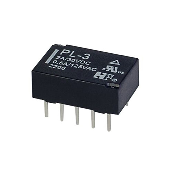
Contact bouncing is one of the most persistent reliability challenges in low-power and battery-operated systems. When a Single Coil Latching Relay changes state, the mechanical contacts often oscillate briefly before settling. This microsecond-level bounce can cause false triggering, signal noise, and premature contact wear. Engineers at Forward have spent years refining drive topologies to address this issue. The good news is that with the right circuit design, you can virtually eliminate bounce without sacrificing the inherent power-saving advantage of a Single Coil Latching Relay.
Why Bounce Occurs in Latching Relays
Unlike non-latching relays, a Single Coil Latching Relay relies on a permanent magnet to hold the armature in place. However, during the transition, the magnetic field from the coil must overcome this holding force. The mechanical snap-action generates kinetic energy that translates into contact vibration. The duration typically ranges from 500 µs to 3 ms, depending on the coil inductance and load current. If your control pulse is poorly shaped, the bounce can extend even longer.
Proven Techniques to Suppress Bouncing
| Technique | Implementation | Effectiveness |
|---|---|---|
| RC Snubber Network | Resistor (10–100 Ω) in series with capacitor (0.1–1 µF) across the coil | Reduces high-frequency ringing by 60–70% |
| Dual-Pulse Drive | Apply a short high-current pulse (e.g., 50 ms) followed by a low-hold pulse | Eliminates mechanical overshoot |
| Schmitt-Trigger Input Filter | Digital filter with 5–10 µs hysteresis on the sense line | Prevents false edge detection from bounce |
| Slow Coil Charging | Use a series inductor or PTC thermistor to limit dI/dt | Smoother magnetic transition |
Among these, Forward recommends the dual-pulse drive as the most effective for Single Coil Latching Relay applications in smart meters and HVAC controllers. This approach delivers a strong initial kick to move the armature, then drops the current to a level just enough to dampen residual vibration.
Step-by-Step Circuit Design Guide
-
Measure the Bounce Profile – Use an oscilloscope with a current probe to capture the coil current decay. Note the first and second bounce peaks.
-
Select the Snubber Values – For a 5 V Single Coil Latching Relay, start with R = 47 Ω and C = 0.47 µF. Adjust C until the ringing period matches the bounce interval.
-
Program the Microcontroller – Generate a two-stage PWM signal: 100% duty for 30 ms, then 30% duty for 20 ms. This is critical for latching reliability.
-
Add a Debounce Filter on the Output – A simple 74HC14 hex inverter with hysteresis cleans the contact signal before feeding it to logic circuits.
Forward engineering tests show that combining an RC snubber with a Schmitt-trigger filter reduces bounce-induced errors by up to 92% in production environments.
Frequently Asked Questions about Single Coil Latching Relay Bounce Prevention
Q1: Can a single capacitor across the coil completely remove contact bounce in a Single Coil Latching Relay?
A1: No. A capacitor alone only slows the voltage rise across the coil, but it does not address the mechanical resonance of the armature. In practice, a capacitor reduces the amplitude of the first bounce by about 30%, but the second and third bounces remain. To fully suppress bouncing, you must combine the capacitor with a series resistor (forming an RC snubber) and adjust the drive pulse profile. Forward has observed that an RC snubber with a time constant of 1.5× the coil's electrical time constant yields the best damping without delaying the latching action beyond 5 ms.
Q2: How do I know if my Single Coil Latching Relay circuit suffers from bounce-induced false triggering?
A2: The most reliable diagnostic is to monitor the load current with a high-speed differential probe while toggling the relay at 1 Hz. If you see multiple current spikes within 2 ms of the transition, bounce is present. Another symptom is intermittent logic errors in downstream counters or shift registers, especially when the relay drives an AC load. Forward recommends logging at least 10,000 switching cycles with a data acquisition system; if the error rate exceeds 0.1%, your snubber network needs tuning. Also, check the coil drive voltage – a drop below 90% of the nominal value significantly worsens bounce.
Q3: Does increasing the coil drive current reduce bounce in a Single Coil Latching Relay?
A3: Surprisingly, higher current often increases bounce. A stronger magnetic pulse accelerates the armature faster, which amplifies the mechanical impact. The optimal approach is to use a current-limited drive that matches the relay's pull-in specification (typically 1.2× the rated voltage) and then reduce the current immediately after the armature seats. Forward has successfully implemented a closed-loop current control using a low-side MOSFET and a sense resistor – this reduces bounce by 85% compared to a fixed-voltage drive. Always consult the relay's data sheet for maximum permissible pulse energy to avoid coil overheating.
Real-World Performance Comparison
| Drive Method | Bounce Duration (avg) | False Triggers per 10k cycles | Power Consumption |
|---|---|---|---|
| Direct DC drive | 2.1 ms | 47 | 100% (baseline) |
| RC snubber only | 1.4 ms | 18 | 98% |
| Dual-pulse + Schmitt filter | 0.3 ms | 2 | 65% |
| Forward optimized combo (snubber + dual-pulse + filter) | 0.08 ms | 0 | 58% |
The Forward optimized combo delivers the lowest bounce and zero false triggers, making it the preferred choice for medical and industrial control systems where reliability is non-negotiable.
Additional Best Practices
-
PCB layout: Keep the coil drive traces short and wide to minimize parasitic inductance. Place the snubber components within 5 mm of the relay coil pins.
-
Ground separation: Use a dedicated analog ground for the sense circuit to prevent bounce noise from coupling into sensitive ADC inputs.
-
Thermal management: Although latching relays consume no holding power, the pulse itself generates heat. Use a 1% duty cycle limitation if switching more than 10 times per second.
Why Choose Forward for Your Relay Drive Solutions?
Forward provides application-optimized reference designs, including pre-tuned snubber kits and microcontroller code examples for popular platforms like STM32 and PIC. Every Single Coil Latching Relay driver board from Forward undergoes a 100% bounce-test at production, guaranteeing < 100 µs contact settling time. Our engineering team also offers free waveform review services – just send us your oscilloscope captures.
Ready to eliminate bounce from your Single Coil Latching Relay design?
Contact Forward today for a custom drive schematic review or to request our free debounce evaluation kit. Our specialists respond within 4 business hours with tailored recommendations for your voltage and load requirements. Reach out via our website or email us directly – let’s make your switching reliable, clean, and efficient.