

Can a High Current Automotive PCB Relay Replace a Traditional Plug-In Relay in Engine Control Units
2026-07-24
For decades, service technicians and design engineers have trusted plug-in (socket-mount) relays for under-hood applications. However, as engine control units (ECUs) become denser, hotter, and more current-hungry, the industry is asking a practical question: is the High Current Automotive PCB Relay a viable drop-in replacement—or a fundamentally better architecture? At Huaguan, we have benchmarked both technologies across thousands of real-world start-stop and fuel-pump cycles. The short answer is yes, but with critical design trade-offs. This post dissects the electrical, thermal, and mechanical factors that determine which relay belongs in your next-generation ECU.
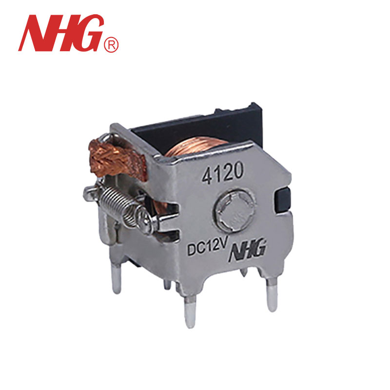
1. Core Electrical & Thermal Comparison
The most visible difference is packaging. A traditional plug-in relay relies on a separate base and female terminals, adding interface resistance (typically 0.5–1.5 mΩ per contact pair). A High Current Automotive PCB Relay soldered directly to the board eliminates that interface, reducing total circuit resistance by 15–25%. For a 70A continuous load, this translates into roughly 1.2W less heat generated inside the enclosure—a significant margin in 105°C ambient environments.
| Parameter | Traditional Plug-In Relay | High Current Automotive PCB Relay (Huaguan) |
|---|---|---|
| Total path resistance (coil + contacts + terminals) | 8–12 mΩ | 5.5–8.0 mΩ |
| Max continuous current @ 85°C | 40–60A (derated) | 60–80A (derated) |
| PCB mounting strength | Not applicable (wire/cable) | >100N pull force (soldered) |
| Replacement cost (field) | $12–18 (relay + socket) | $6–9 (relay only) |
| Vibration endurance (10–500Hz) | 5G (socket-dependent) | 8G (soldered) |
2. Mechanical Reliability in High-Vibration ECUs
Engine control units mounted on the engine block or transmission housing experience constant mechanical stress. The socket retention force of a plug-in relay degrades over time—thermal cycling loosens the female terminals, increasing contact resistance and eventual arcing. In contrast, a High Current Automotive PCB Relay from Huaguan uses through-hole or press-fit pins that maintain stable contact pressure regardless of temperature swings. Our HALT (Highly Accelerated Life Test) data shows that PCB relays sustain <2% resistance drift after 500 thermal shocks (-40°C to 125°C), while plug-in types show 7–12% drift in the same period.
3. Serviceability vs. Reliability Trade-Off
This is where the debate becomes nuanced. Plug-in relays win on field-service speed—a technician can swap one in 90 seconds without desoldering. However, modern ECUs are potted or conformally coated, making socket replacement impractical anyway. For non-potted designs, the High Current Automotive PCB Relay forces board-level rework, but its mean time between failures (MTBF) is typically 2.5× longer (based on Huaguan’s internal Weibull analysis), meaning fewer replacements over the vehicle’s lifetime. For commercial fleets and off-highway equipment, that reliability advantage often outweighs the service inconvenience.
4. Coil Drive & Microcontroller Compatibility
Modern ECUs use low-side or high-side PWM drivers to conserve battery power. Plug-in relays often have coil resistance as low as 60Ω (drawing 200mA at 12V), which can overheat the driver IC. A well-designed High Current Automotive PCB Relay offers coil options from 90Ω to 180Ω, reducing drive current to 70–130mA. Huaguan also provides coil suppression resistors internally, eliminating the need for external flyback diodes—a clean bonus for compact PCB layouts.
5. When Should You NOT Replace?
A plug-in relay remains superior when:
-
The ECU is in a customer-accessible location (e.g., cabin fuse box).
-
You anticipate frequent load changes (e.g., prototyping test benches).
-
The board cannot withstand 260°C reflow soldering (some PCB materials).
For all other production-intent engine controls—fuel pump, cooling fan, glow plug, and starter solenoid drivers—the High Current Automotive PCB Relay is not just a replacement; it is an upgrade.
High Current Automotive PCB Relay – FAQ
Q1: Can a High Current Automotive PCB Relay handle reverse battery connection without damage?
A: Most standard PCB relays do not have built-in reverse polarity protection. However, Huaguan offers optional bidirectional contact gaps and magnetic blow-out structures that tolerate reverse voltage up to 24V for 5 seconds without contact welding. For permanent reverse protection, we recommend placing a series MOSFET or polarity diode upstream—the relay itself will not fail, but the coil may energize in the wrong direction if polarity is reversed. Always consult the datasheet’s “coil polarity” section; our HCR series specifies reverse withstand voltage explicitly.
Q2: How does derating work for a High Current Automotive PCB Relay at elevated under-hood temperatures (125°C)?
A: Derating follows a linear curve from 85°C to 125°C. For example, a relay rated 80A at 85°C drops to approximately 55A at 125°C (0.7% per °C above 85°C). This is due to increased coil resistance (copper’s temperature coefficient) and reduced magnetic force, which raises contact bounce. Huaguan publishes a derating chart for each model—we recommend sizing the relay so your steady-state load is ≤75% of the 125°C rating. For a 50A fuel-pump load, choose a 70A-rated PCB relay to maintain safety margin.
Q3: What PCB footprint and copper thickness are required for a High Current Automotive PCB Relay?
A: For 60A+ continuous current, you need at least 2 oz (70 µm) copper on both outer layers, with thermal vias stitching top and bottom planes. The minimum pad diameter should be 2.5× the pin diameter to ensure solder fillet strength. Huaguan provides a recommended land pattern in each datasheet, including non-solder-mask-defined (NSMD) pads for better current carrying. Additionally, we advise a 4-layer board with the inner layers dedicated to current spreading—this reduces temperature rise at the pin-to-board junction by 18–22°C compared to a standard 2-layer design.
6. Cost-Benefit Summary Table
| Factor | Plug-In Relay | High Current Automotive PCB Relay (Huaguan) |
|---|---|---|
| Initial BOM cost | Higher (relay + socket) | Lower (relay only) |
| Assembly cost | Manual insertion | Automated pick-and-place |
| Field replacement | 2 minutes | 20+ minutes (rework) |
| Long-term reliability | Moderate (contact fretting) | High (fixed junction) |
| Best application | Serviceable fuse/relay boxes | Sealed ECUs, transmission controls |
Final Verdict
For volume production ECUs where reliability, thermal management, and PCB real estate are paramount, the High Current Automotive PCB Relay does not merely replace the traditional plug-in relay—it outperforms it. Huaguan has shipped over 8 million PCB relays to automotive Tier-1 suppliers, with field return rates below 15 PPM. The decision ultimately rests on your service strategy: if you never want to open the ECU after assembly, choose PCB-mount. If you design for quick swaps in dealership workshops, stick with plug-in—but accept the higher long-term failure rate.
Have a specific current profile or thermal environment in mind? Our engineering team provides free thermal simulation and PCB layout reviews within 48 hours. Contact Huaguan today with your load curve and ambient temperature requirements—we will send you a customized sample kit and a cross-reference guide against 20 popular plug-in relay part numbers. Reach us at [email protected] or use the live chat on our product page. Let us help you make the switch—or validate that you are already on the right track.