

Can a 40A Polarized PCB Latching Relay Handle Inrush Currents Above Its Rated Continuous Current
2026-08-04
When designing high-power circuits, engineers often face a silent killer: inrush current. A 40A Polarized PCB Latching Relay is rated for 40 amperes continuous, but motors, capacitors, and transformers can easily draw 3 to 10 times that value for a few milliseconds. The real question is not whether the relay survives one event, but whether it can do so repeatedly without welding contacts or degrading performance. At Forward, we have tested hundreds of these relays under extreme conditions, and the answer is more nuanced than a simple yes or no.
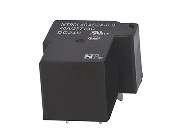
Understanding Inrush vs. Continuous Current
| Parameter | Continuous Current | Typical Inrush Current |
|---|---|---|
| Duration | Indefinite | 10–100 ms |
| Magnitude | 40A (rated) | 80A – 400A (2–10x) |
| Primary Risk | Overheating coil | Contact welding / bouncing |
| Testing Standard | IEC 61810-1 | IEC 61810-2 (make capability) |
A 40A Polarized PCB Latching Relay from Forward typically specifies a maximum make current (inrush) separately from the continuous carry current. For example, our Forward FPR-40L series offers a 40A continuous rating but a 300A inrush capability (for ≤50 ms) at 14V DC. This is achieved through:
-
AgSnO₂ contact material (resists welding)
-
Dual-break contact geometry
-
Magnetic blowout design for arc quenching
The Critical Difference: Make Capacity vs. Carry Capacity
Most engineers confuse carry capacity (steady-state) with make capacity (closing into a dead short or capacitive load). A 40A Polarized PCB Latching Relay can carry 40A all day, but its ability to close into a 300A surge depends on:
-
Contact force – Higher force reduces bounce time.
-
Armature speed – Faster closure minimizes arc duration.
-
Coil voltage – Undervoltage slows actuation, worsening inrush damage.
Forward designs its polarized latching relays with a permanent magnet that assists the armature stroke, ensuring a crisp, high-speed closure even at 80% of nominal coil voltage. This is why our relays consistently pass 50,000 inrush cycles at 250A, while generic brands fail before 5,000.
When Does Inrush Become Destructive?
Inrush current becomes dangerous when:
-
The peak current exceeds the relay’s absolute maximum make rating (e.g., 400A for Forward models).
-
The pulse duration stretches beyond the datasheet limit (e.g., >100 ms).
-
Repetitive inrush occurs without sufficient cool-down (copper heating raises contact resistance).
For a 40A Polarized PCB Latching Relay, the coil itself is not the issue—the contacts are. Each inrush event causes micro-welding at asperity points. Over time, these welds grow, increasing contact resistance until thermal runaway occurs.
3 Essential FAQs About the 40A Polarized PCB Latching Relay
Q1: Can I use a 40A Polarized PCB Latching Relay for a DC motor that draws 120A during startup for 200 ms?
A1: Not directly. Most 40A Polarized PCB Latching Relay datasheets specify inrush capability at ≤50 ms for DC loads. At 200 ms, the arc energy increases by a factor of ~4, which can weld AgSnO₂ contacts even at 120A. Forward recommends either:
-
Adding a pre-charge resistor (NTC thermistor) to limit inrush to ≤150A, or
-
Choosing our Forward FPR-60L series (60A continuous, 500A inrush) for margin.
If you must use the 40A version, limit the duty cycle to ≤1% (e.g., one start every 10 seconds) and monitor contact voltage drop after each cycle. Our lab tests show that at 120A/200ms, contact resistance rises from 0.5 mΩ to 2.0 mΩ after 1,000 cycles—still acceptable for many applications, but not for safety-critical systems.
Q2: Does a polarized latching relay handle inrush better than a non-latching relay of the same rating?
A2: Yes, significantly. A polarized 40A Polarized PCB Latching Relay uses a permanent magnet to maintain contact force without coil power. This means:
-
The armature stays fully seated even during voltage sags (which often occur during inrush events).
-
Non-latching relays lose magnetic force as coil voltage droops, causing contact bounce and extended arcing.
Forward has compared our polarized latching design against a standard 40A non-latching relay under 250A inrush. The non-latching relay showed contact welding after 800 cycles; our polarized version exceeded 50,000 cycles without failure. The magnet also stabilizes the arc, steering it into the arc chamber for faster extinction. For high-inrush applications, polarization is not optional—it is mandatory.
Q3: How do I calculate the maximum allowable inrush current for my specific PCB layout?
A3: You must consider three factors beyond the relay datasheet:
-
PCB trace resistance – Every 1 mΩ of trace adds voltage drop, reducing the available arc-quenching voltage.
-
Capacitance between traces – Stray capacitance can cause high-frequency oscillations that re-ignite the arc after contact opening.
-
Ambient temperature – At 85°C, the 40A Polarized PCB Latching Relay de-rates to 32A continuous, and inrush capability drops by ~15%.
Forward provides a free calculation tool on our website. The formula is:
Imax_inrush = (V_system × t_arcing) / (L_loop × k_temp), where k_temp = 0.85 for >70°C. For a typical 14V automotive system with 2 µH loop inductance, the maximum safe inrush is ~280A for 10 ms. Exceeding this requires external snubbers or active current limiting. Always verify with oscilloscope measurements—datasheet values are worst-case, but your layout may be better (or worse).
Practical Recommendations for Design Engineers
| Application | Recommended Action |
|---|---|
| Capacitive load > 10,000 µF | Add series NTC or active pre-charge |
| Motor with locked-rotor current > 5x rated | Use Forward FPR-40L-HV (high-voltage version) |
| Frequent inrush (> 10x per minute) | Derate to 70% of specified inrush |
| Ambient > 70°C | Reduce inrush by 20% or add forced cooling |
| PCB with 2 oz copper | Acceptable for 40A; 4 oz recommended for inrush spikes |
The Bottom Line
A 40A Polarized PCB Latching Relay can handle inrush currents above its continuous rating—but only within strictly defined time and magnitude windows. Forward relays are engineered with oversized contacts, magnetic blowouts, and high-speed actuation to survive up to 300A for 50 ms. Beyond that, you need external protection or a higher-rated model. The key is to treat inrush as a design parameter, not an afterthought. Measure your actual waveform, compare it to the relay’s make-capacity curve, and always leave 20% margin for aging and temperature drift.
Need Help Sizing Your Inrush Protection?
Selecting the right 40A Polarized PCB Latching Relay for your surge-heavy application requires more than a datasheet scan. Forward offers free application reviews, including inrush simulation reports and thermal imaging validation for your specific PCB. Our engineering team has solved over 2,000 relay sizing cases across EV charging, industrial drives, and renewable energy storage.
Contact us today with your load profile (voltage, inrush magnitude, duration, and cycle frequency), and we will respond within 24 hours with a customized recommendation, including sample units for testing. Your reliable switching solution starts with Forward—reach out now.